
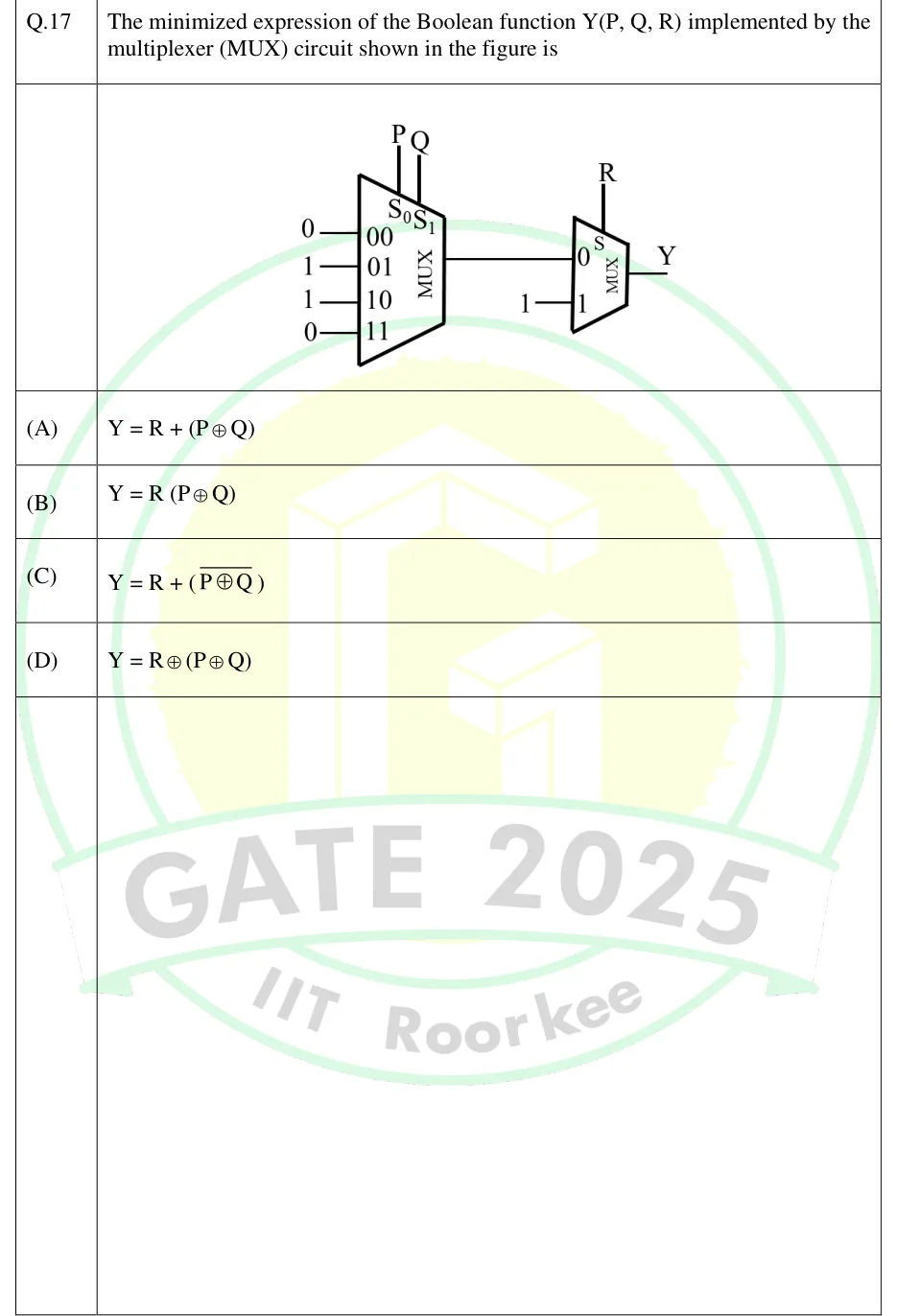
The minimized expression of the Boolean function Y(P, Q, R) implemented by the multiplexer (MUX) circuit shown in the figure is
 Tap to open full size
Figure description
Two multiplexers in cascade. First MUX (4:1): select lines labelled S_0 (driven by P) and S_1 (driven by Q), with the select bits read as S_0S_1. Data inputs: input 00 = 0, input 01 = 1, input 10 = 1, input 11 = 0. Its output goes to data input 0 of a second MUX (2:1). Second MUX: select line S driven by R; data input 0 = output of the first MUX, data input 1 = constant 1. The output of the second MUX is Y.
- (A)
- (B)
- (C)
- (D)