
IAE Academy

GATE 2026 EC Q.49: solution and answer

GATE 2026 · ECQ.49 · 2 marks · MCQ

A shift-left Shift Register (SR) and a D flip-flop are connected to a synchronized clock as shown in the Figure. Assume that the SR and D flip-flops are initially cleared and the XOR gate has no propagation delay.

Which of the following options gives the correct binary representation of the content of the shift register immediately after the clock transition (positive edge)?
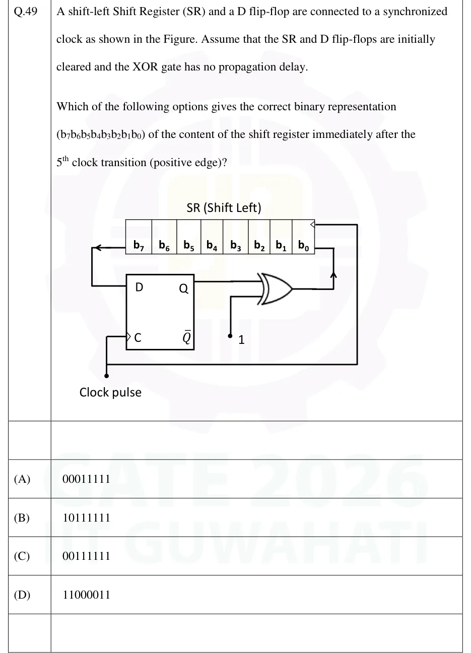
GATE 2026 EC question 49: An 8-bit shift register labelled 'SR (Shift Left)' with cells b7 b6 b5 b4 b3 b2 b1 b0 from left to right.Tap to open full size
Figure from the GATE 2026 EC paper. It is part of the question.
Figure description

An 8-bit shift register labelled 'SR (Shift Left)' with cells b7 b6 b5 b4 b3 b2 b1 b0 from left to right. Its clock input (a small triangle) is at the top-right corner next to b0. The serial output is taken from b7 (an arrow leaves b7 to the left) and is wired down to the D input of a D flip-flop. The flip-flop's Q output goes to one input of a 2-input XOR gate. The other XOR input is tied to constant logic 1. The XOR output is wired up into b0 (an arrow points up into b0), so it is the serial input of the shift-left register. The flip-flop's Q-bar output is unconnected. A single 'Clock pulse' line drives the flip-flop's clock input C (positive edge, no bubble). The same line runs along the bottom and up the right side to the shift register's clock input, so both are clocked together.

  1. (A)

  2. (B)

  3. (C)

  4. (D)

Answer and solution

ANSWER

Immediately after the 5th positive edge the register holds . The answer is option (A).

Official answer: ASource: Official answer key, GATE 2026 EC (IIT Guwahati)

  1. Read the connections. The serial input of the shift-left register is the XOR output: (overline = complement). The D flip-flop samples the bit being shifted out: . On each positive edge, .

  2. Synchronous update rule. The register and the flip-flop share one clock edge, so every new value is computed from the values present just before that edge. The XOR has no delay, so it simply keeps at the serial input.

  3. Initial state: and , so the serial input is .

  4. Clock 1: and , giving .

  5. Clocks 2 to 4: before each of these edges , so stays 0 and another 1 enters at each time: .

  6. Clock 5: just before the edge and , so another 1 enters: .

  7. Why the feedback never acts here. The first 1 enters at edge 1 and does not reach until edge 8, so cannot become 1 before edge 9. The first five edges therefore just shift in five 1s from the right, and the content is : option (A).

KEY IDEA

XOR with a constant 1 is an inverter, so the serial input is . samples , which stays 0 until a 1 has travelled all 8 cells, so for the first 8 edges and a 1 shifts in at on every edge.

WATCH OUT FOR

Taking the serial input as instead of leaves the register at all zeros, which is not an option. Filling from the end, as if it were a shift-right register, gives , also not an option. Counting one edge too many (for example, treating the initial clear as a clock) gives six 1s, , which is the trap option (C).

From the GATE 2026 EC paper. Every question of this paper · Download the full paper · All 30 Sequential questions, with notes

More Sequential questions