IAE Academy

IN THE EE SYLLABUS

Energy conversion and DC machines

GATE EE study notes on "Energy conversion and DC machines": field energy, coenergy and force/torque in singly and doubly excited systems; DC machine EMF, torque and terminal equations; the separately excited, shunt, series and compound family; generator and motor characteristics, self-excitation and regulation; speed control, starting and braking; losses, efficiency, armature reaction and commutation. It closes with 3 worked examples and 5 original GATE-style practice questions.

8 previous-year questions · 8 solved · 5 practice questions

Electromechanical energy conversion principles

An electromechanical energy converter stores energy in a magnetic field. It exchanges that energy between an electrical port (voltage and current) and a mechanical port (force or torque, and displacement). Mechanical force (or torque) can be found in two equivalent ways:

  • from the magnetic coenergy, differentiated at constant current;
  • from the magnetic field energy, differentiated at constant flux linkage, with a minus sign.

At any given operating point both give the same instantaneous force.

STORED FIELD ENERGY

is the flux linkage and is the (fixed) mechanical position. Graphically, is the area between the – curve and the -axis.

COENERGY (SINGLY EXCITED SYSTEM)

The coenergy is the area between the – curve and the -axis, at a fixed position .

ENERGY–COENERGY RELATION

This holds for any (linear or saturated) – curve. In a magnetically linear system numerically.

FORCE, CONSTANT-CURRENT FORM

Coenergy is written as a function of and , and the partial derivative is taken with held fixed. This form is convenient when the excitation current is known.

FORCE, CONSTANT-FLUX-LINKAGE FORM

Field energy is written as a function of and , and the partial derivative is taken with held fixed. Note the minus sign. This gives the same force as the constant-current form.

TORQUE

This is the rotational analogue of the force expressions. is the mechanical angle in radians and is in N m.

LINEAR (UNSATURATED) SINGLY EXCITED CASE

This applies when the system is magnetically linear, so that . The force acts in the direction that increases the inductance, i.e. that reduces the reluctance of the magnetic path.

DOUBLY EXCITED SYSTEM (MAGNETICALLY LINEAR)

The first two terms are reluctance torques. They exist only if a self-inductance varies with (saliency). The third term is the mutual (alignment) torque, which needs both windings excited. In a machine with a uniform air gap only the mutual term survives.

  1. Constant current, linear system: for a small displacement, the electrical input is . Half of it, , increases the stored field energy, and the other half is converted to mechanical work.

  2. Constant flux linkage: no electrical energy enters (), so all the mechanical work comes from the stored field energy, which decreases.

  3. Energy balance in general: electrical energy input = increase in stored field energy + mechanical work done (losses neglected).

EXAM TIP

Sign convention:

  • At constant current, the force or torque acts in the direction that increases the coenergy. In a linear system this means increasing inductance, or decreasing air-gap reluctance.
  • At constant flux linkage, the force acts in the direction that decreases the stored field energy.

Differentiating with a plus sign gives the wrong sign.

DC machine EMF and torque equations

A DC machine's armature winding rotates in the field flux, so it generates an EMF. When it carries current, it also produces torque. Both quantities depend on the same winding constants, so the EMF and torque equations share the same structure.

GENERATED EMF

  • = number of poles
  • = flux per pole (Wb)
  • = total number of armature conductors
  • = speed (rpm)
  • = number of parallel paths: for a simplex lap winding, and for a simplex wave winding whatever the value of

ELECTROMAGNETIC TORQUE

is the total armature current. With in Wb and in A, is in N m. , and are the same as in the EMF equation.

COMPACT FORM

is the mechanical angular speed in rad/s. is a fixed constant of the winding, so both and are proportional to .

ELECTROMAGNETIC POWER AND TORQUE

The electromagnetic (developed) power equals the electromagnetic torque times the speed, in both modes. Shaft power differs from it by the rotational (core and mechanical) losses.

TERMINAL VOLTAGE EQUATIONS

is the resistance of the armature circuit. It includes the series-field (and interpole) winding resistance where those windings carry , as in series and long-shunt compound machines. The brush contact drop is treated as a constant voltage when one is given, and neglected otherwise. It is subtracted for a generator and added for a motor.

CURRENTS IN A SHUNT MACHINE

is the line (load or supply) current and is the total resistance of the shunt field circuit. In a series machine, .

  1. Generating mode: a prime mover drives the armature, , and armature current flows out of the + terminal.

  2. Motoring mode: the electrical supply drives the armature, , and armature current flows into the + terminal.

  3. Armature power balance (brush drop neglected). Generator: . Motor: .

  4. Generator shaft input = + rotational losses. Motor shaft output = − rotational losses.

Types of DC machines and their field connections

DC machines are classified by how the field winding is excited and connected relative to the armature. This decides how the flux varies with load, and so how , , speed and torque behave.

Type

Field connection

Field current

Behaviour

Separately excited

Field fed from an independent DC source

Set independently of ; constant if the field supply is constant

Flux can be controlled independently of load; the most flexible speed control

Shunt

Field winding (many turns, high resistance) in parallel with the armature

; nearly constant if is constant

Nearly constant-speed motor; generator with a mildly drooping voltage

Series

Field winding (few turns, low resistance) in series with the armature

; flux rises with load current (roughly in proportion, below saturation)

As a motor: high starting torque, speed falls steeply with load, must never run at no load

Compound (cumulative)

Shunt field plus series field, with the series MMF aiding the shunt MMF

Shunt: about . Series: (long shunt) or (short shunt), less any current bypassed by a diverter

Between shunt and series behaviour

Compound (differential)

Series MMF opposes the shunt MMF

As for cumulative, with the series field reversed

As a motor, speed can rise with load and operation is prone to instability; as a generator, voltage falls steeply with load

EXAM TIP

As generators, shunt, series and compound machines are self-excited: their own armature supplies the field current. Only the separately excited machine uses an external field supply. As motors, the shunt, series and compound field windings are fed from the same supply as the armature.

Characteristics of DC generators and motors

The characteristics describe how, for a given type of excitation, one quantity varies as the load current changes:

  • generators: the terminal voltage (external characteristic);
  • motors: the speed and the torque.

The open-circuit characteristic (OCC) is a separate curve. It plots against at no load and a fixed speed, and it shows saturation.

  1. Separately excited generator: the terminal voltage droops slightly with load, because of the drop and the demagnetising effect of armature reaction.

  2. Shunt generator: droops more than a separately excited generator. As falls, the field current also falls, which lowers further.

  3. Series generator: the terminal voltage rises with load current as the flux builds up, then falls once saturation and the drop dominate.

  4. Cumulative compound generator: it is over-compounded if full-load voltage exceeds no-load voltage, flat-compounded if they are equal, and under-compounded if it is lower.

  5. Shunt motor: the speed falls only slightly with load, because is nearly constant and drops only a little. Neglecting armature reaction, .

  6. Series motor: below saturation . This gives and roughly (so roughly). Starting torque is very high and speed at light load is dangerously high, so a series motor must never be run at no load or through a belt that can slip off.

  7. Cumulative compound motor: starting torque is higher than a shunt motor's, and the no-load speed is safe and finite, unlike a series motor's.

Motor

Speed vs load

Torque vs

Starting torque

Shunt

Nearly constant (drops slightly)

(straight line)

Moderate

Series

Falls sharply as load increases

below saturation, tending to in saturation

Very high

Cumulative compound

Drops more than shunt, less than series

Between shunt and series

High

VOLTAGE REGULATION (GENERATOR) AND SPEED REGULATION (MOTOR)

Both are referred to the full-load value. A flat-compounded generator has zero voltage regulation.

  1. Conditions for a self-excited generator to build up voltage:

  2. 1. There must be residual magnetism in the poles.

  3. 2. The field must be connected so that its MMF aids the residual flux. If it opposes the residual flux, reverse the field connections or the direction of rotation.

  4. 3. The field-circuit resistance must be less than the critical field resistance. This is the slope of the initial, linear part of the OCC at the given speed.

  5. 4. The speed must be above the critical speed, which is the speed at which the actual field-circuit resistance equals the critical resistance. For a series generator, the load resistance must also be below its critical value.

Speed control, starting and braking

SPEED EQUATION

This follows directly from , with in rpm. For two operating points of the same machine, . Every speed-control method below can be reasoned from this equation.

  1. Armature voltage control (separately excited motor, field on a constant supply): vary with a controlled rectifier or chopper while is held at rated value. This covers speeds from near zero up to base speed. Because is unchanged, the torque available at rated stays constant (the constant-torque region).

  2. Field control (field weakening, shunt or separately excited motor): reduce the field current, and hence , with at rated value. By the speed equation the speed rises, so this is used above base speed. With limited to rated value by heating, the available torque falls roughly as (the approximately constant-power region).

  3. Armature resistance control: put an external resistance in series with the armature. For a given and load, and therefore fall. It is simple, but it wastes and makes the speed depend strongly on load.

  4. Series motor: a field diverter (a resistance across the series field) reduces the field current and flux, which raises the speed. A tapped field (fewer effective turns) does the same. Series armature resistance reduces the speed.

EXAM TIP

Never connect a DC motor directly across full rated voltage at standstill. At , , so only the small armature-circuit resistance limits the current: , which is dangerously large. A starter puts a resistance in series with the armature and cuts it out in steps as the speed, and hence , builds up. This keeps the current within a safe limit.

  1. Plugging (reverse-current braking): the armature supply connections are reversed while the motor is still rotating. The back EMF and the supply voltage then act in the same direction around the armature circuit, so an extra current-limiting resistance is essential. The energy is dissipated, not returned. The supply must be disconnected at zero speed, or the motor will run up in reverse.

  2. Dynamic (rheostatic) braking: the armature is disconnected from the supply and connected across a resistor, with the field kept excited. The machine runs as a generator on its stored kinetic energy and dissipates it in the resistor.

  3. Regenerative braking (shunt or separately excited machine): the load drives the machine above its no-load speed, as in a descending hoist or a train going downhill. Then , the armature current reverses, and energy is returned to the supply. This is the only one of the three methods that recovers energy. A series motor does not regenerate naturally, because reversing also reverses its field; its field has to be reconnected or separately excited.

Losses, efficiency, armature reaction and commutation

Loss category

Component

Depends on

Variable (copper) losses

Armature-circuit copper loss , including the series-field and interpole windings

Square of the load current

Constant losses

Shunt-field (or separately excited field) copper loss

Constant when and are constant

Constant losses

Iron (core) loss: hysteresis plus eddy current in the armature core

Flux and speed; roughly constant at constant flux and speed

Constant losses

Mechanical loss: bearing friction and windage

Speed; roughly constant at constant speed

Stray load loss

Extra core and eddy loss caused by armature-reaction flux distortion under load

Load; included only when a value is given

EFFICIENCY

For a generator, the output is electrical terminal power and the input is mechanical shaft power. For a motor it is the reverse.

CONDITION FOR MAXIMUM EFFICIENCY

Efficiency is maximum when the variable copper loss equals the constant losses.

  • Exact when the terminal voltage is constant and the same current flows as output current and through . Example: a separately excited generator, with and .
  • Approximate for shunt machines, where . It is used there with .

Armature reaction is the effect of the armature's own MMF on the main field. It has two parts:

1. Cross-magnetising effect. Ignoring saturation, this distorts the air-gap flux without changing its net value. It shifts the magnetic neutral axis in the direction of rotation for a generator and against the direction of rotation for a motor.
2. Demagnetising effect. When the pole tips saturate, the strengthened tip gains less flux than the weakened tip loses, so the net flux per pole falls. The net flux also falls if the brushes are shifted off the geometric neutral axis. Either way, the generated EMF or back EMF is lower.

For good commutation, a generator's brushes are shifted forward (with the rotation) and a motor's backward.

ARMATURE-REACTION AMPERE-TURNS PER POLE (BRUSH SHIFT)

is the brush shift from the geometric neutral axis in mechanical degrees, and is the current in each conductor. With no brush shift, and all armature ampere-turns per pole are cross-magnetising.

Commutation is the reversal of current in an armature coil as it passes under a brush. The coil has self-inductance , so the reversal induces a reactance voltage that opposes the change. If it is not neutralised, it causes sparking at the brushes. For linear commutation the current changes from to in the commutation period , and the average reactance voltage is .

  1. Interpoles (commutating poles): narrow poles placed midway between the main poles, with their windings in series with the armature so that their MMF follows the load. They induce a voltage in the commutating coil that cancels the reactance voltage, and they neutralise the cross-magnetising armature MMF in the commutating zone.

  2. Interpole polarity: for a generator, the same as the next main pole ahead in the direction of rotation. For a motor, the same as the main pole just behind, i.e. the one the conductors have just passed.

  3. Compensating winding: conductors in slots in the main pole faces, in series with the armature and carrying current opposite to the armature conductors beneath them. They cancel the cross-magnetising armature MMF under the pole faces. It is used in machines with heavy or rapidly changing loads, together with interpoles.

Worked examples

WORKED EXAMPLE

A 4-pole, lap-wound DC generator has 500 armature conductors and a flux of 0.02 Wb per pole, and runs at 1000 rpm. (a) Find the generated EMF. (b) If the armature current is 20 A, find the electromagnetic torque developed.

Solution
  1. Lap winding, so the number of parallel paths is .

  2. (a) .

  3. (b) N m.

  4. Cross-check with power: and , so N m. This matches. In a generator this electromagnetic torque opposes the prime mover.

Answer: E = 166.67 V, T = 31.83 N m

WORKED EXAMPLE

A 220 V DC shunt motor has armature resistance . Driving a constant-torque load, it takes an armature current of 20 A and runs at 1000 rpm. The field rheostat is adjusted to reduce the flux to 80% of its original value, and the load torque is unchanged. Neglecting armature reaction, find the new armature current and the new steady-state speed.

Solution
  1. The load torque is constant and , so . This gives .

  2. and .

  3. .

  4. . Holding at 20 A would wrongly give 1250 rpm. At constant torque the armature current must rise as the flux falls, and the larger drop slightly reduces the speed gain.

Answer: I_a2 = 25 A, N2 ≈ 1235 rpm

WORKED EXAMPLE

A separately excited DC generator delivers load at a constant terminal voltage of 230 V. Its armature resistance is , and its constant losses (core, mechanical and field copper) total 900 W. Neglecting brush drop and stray load loss, find the armature current at which efficiency is maximum, and the maximum efficiency.

Solution
  1. . This is maximum when is minimum.

  2. Differentiating with respect to : , so .

  3. .

  4. Output . Losses . Input .

  5. , i.e. .

Answer: I_a = 60 A, maximum efficiency ≈ 88.46%

PREVIOUS-YEAR QUESTIONS

8 questions from the EE and IN papers

Try each question first, then open the answer. We placed each question under a topic ourselves; the exam paper does not label topics.

See these papers in full: GATE EE 2025 · GATE EE 2023 · GATE EE 2022 · GATE EE 2020 · GATE EE 2018 · GATE IN 2023

GATE 2025 EE Q.44

GATE 2025 · EEQ.44 · 2 marks · MCQ

A DC series motor with negligible series resistance is running at a certain speed driving a load, where the load torque varies as cube of the speed. The motor is fed from a 400 V DC source and draws 40 A armature current. Assume linear magnetic circuit. The external resistance, in Ω, that must be connected in series with the armature to reduce the speed of the motor by half, is closest to

  1. (A)

    23.28

  2. (B)

    4.82

  3. (C)

    46.7

  4. (D)

    0

Answer and solution
See the question in the paper
GATE 2025 EE Q.44: answer and solution

GATE 2023 EE Q.22

GATE 2023 · EEQ.22 · 1 mark · MCQ

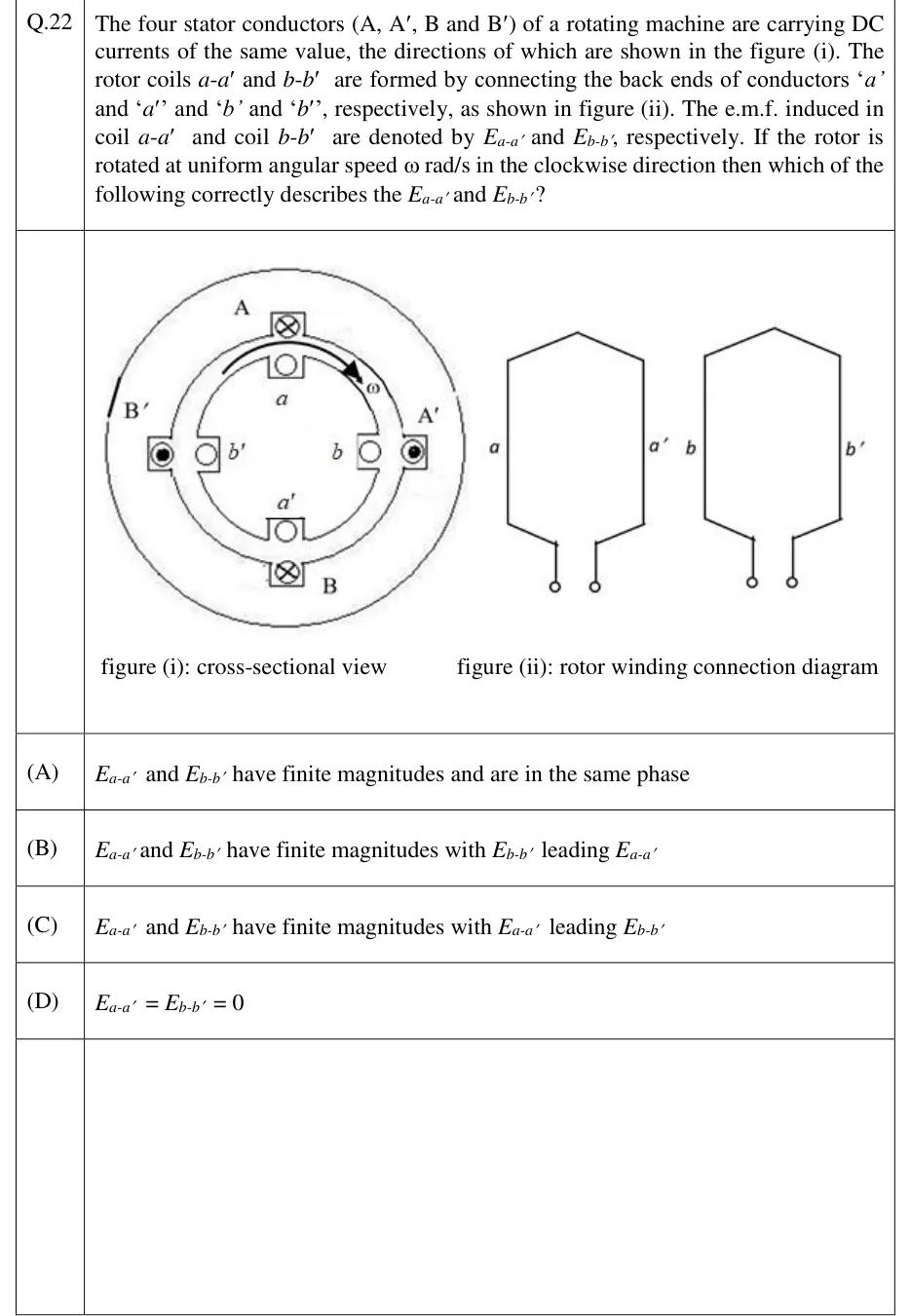
The four stator conductors (A, A′, B and B′) of a rotating machine are carrying DC currents of the same value, the directions of which are shown in the figure (i). The rotor coils - and - are formed by connecting the back ends of conductors '' and '' and '' and '', respectively, as shown in figure (ii). The e.m.f. induced in coil - and coil - are denoted by and , respectively. If the rotor is rotated at uniform angular speed rad/s in the clockwise direction then which of the following correctly describes the and ?

GATE 2023 EE question 22: Two sub-figures.Tap to open full size
Figure from the GATE 2023 EE paper. It is part of the question.
Figure description

Two sub-figures. Figure (i), cross-sectional view: an outer stator ring and an inner rotor ring share a common centre. Going clockwise from the top, the outer (stator) conductors are A (top, current into the page, shown ⊗), A′ (right, current out of the page, shown ⊙), B (bottom, current into the page, ⊗), and B′ (left, current out of the page, ⊙) — i.e. diametrically opposite stator conductors A B carry current in the same direction (into page), and A′ B′ carry current in the same opposite direction (out of page). Just inside each stator conductor, at the same angular position, sits a rotor conductor: a (top, just under A), b (right, just under A′), a′ (bottom, just above B), b′ (left, just above B′). A curved arrow ω between a and A′ shows the rotor spinning clockwise. Figure (ii), rotor winding connection diagram: two separate hexagonal (coil-shaped) loops, each drawn with two front leads coming down to small circles (terminals). The left loop is labelled with terminal 'a' at its lower-left lead and 'a′' at its lower-right lead (their far/back ends are joined inside the loop, forming coil a-a′). The right loop is labelled 'b' at its lower-left lead and 'b′' at its lower-right lead, similarly joined at the back to form coil b-b′.

  1. (A)

    and have finite magnitudes and are in the same phase

  2. (B)

    and have finite magnitudes with leading

  3. (C)

    and have finite magnitudes with leading

  4. (D)

Answer and solution
GATE 2023 EE Q.22: answer and solution

GATE 2023 EE Q.30

GATE 2023 · EEQ.30 · 1 mark · NAT

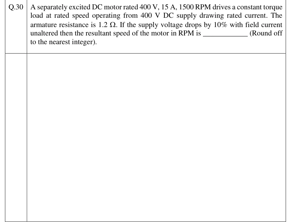
A separately excited DC motor rated 400 V, 15 A, 1500 RPM drives a constant torque load at rated speed operating from 400 V DC supply drawing rated current. The armature resistance is 1.2 Ω. If the supply voltage drops by 10% with field current unaltered then the resultant speed of the motor in RPM is ____________ (Round off to the nearest integer).

Answer and solution
See the question in the paper
GATE 2023 EE Q.30: answer and solution

GATE 2023 IN Q.35

GATE 2023 · INQ.35 · 1 mark · NAT

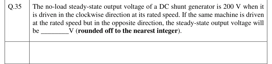
The no-load steady-state output voltage of a DC shunt generator is 200 V when it is driven in the clockwise direction at its rated speed. If the same machine is driven at the rated speed but in the opposite direction, the steady-state output voltage will be ________V (rounded off to the nearest integer).

Answer and solution
See the question in the paper
GATE 2023 IN Q.35: answer and solution

GATE 2022 EE Q.62

GATE 2022 · EEQ.62 · 2 marks · NAT

A 280 V, separately excited DC motor with armature resistance of 1 Ω and constant field excitation drives a load. The load torque is proportional to the speed. The motor draws a current of 30 A when running at a speed of 1000 rpm. Neglect frictional losses in the motor. The speed, in rpm, at which the motor will run, if an additional resistance of value 10 Ω is connected in series with the armature, is ________. (round off to nearest integer)

Answer and solution
See the question in the paper
GATE 2022 EE Q.62: answer and solution

GATE 2020 EE Q.28

GATE 2020 · EEQ.28 · 2 marks · MCQ

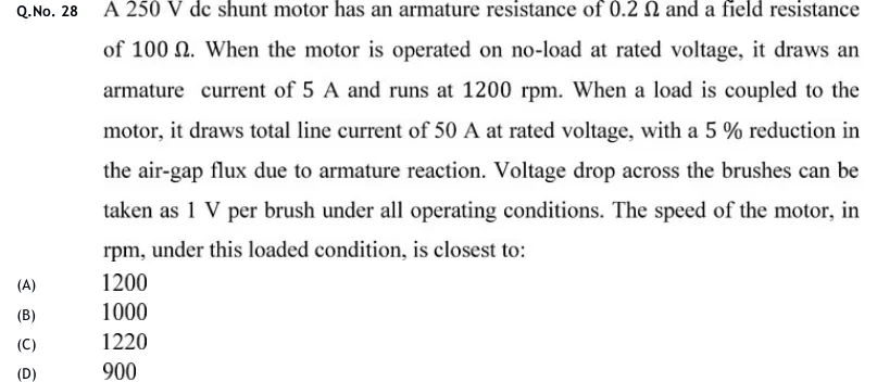
A 250 V dc shunt motor has an armature resistance of and a field resistance of . When the motor is operated on no-load at rated voltage, it draws an armature current of 5 A and runs at 1200 rpm. When a load is coupled to the motor, it draws total line current of 50 A at rated voltage, with a 5% reduction in the air-gap flux due to armature reaction. Voltage drop across the brushes can be taken as 1 V per brush under all operating conditions. The speed of the motor, in rpm, under this loaded condition, is closest to:

  1. (A)

    1200

  2. (B)

    1000

  3. (C)

    1220

  4. (D)

    900

Answer and solution
See the question in the paper
GATE 2020 EE Q.28: answer and solution

GATE 2018 EE Q.24

GATE 2018 · EEQ.24 · 1 mark · NAT

A separately excited dc motor has an armature resistance . The field excitation is kept constant. At an armature voltage of 100 V, the motor produces a torque of 500 Nm at zero speed. Neglecting all mechanical losses, the no-load speed of the motor (in radians/s) for an armature voltage of 150 V is ______ (up to 2 decimal places).

Answer and solution
See the question in the paper
GATE 2018 EE Q.24: answer and solution

GATE 2018 EE Q.52

GATE 2018 · EEQ.52 · 2 marks · NAT

A 200 V DC series motor, when operating from rated voltage while driving a certain load, draws 10 A current and runs at 1000 r.p.m. The total series resistance is 1 Ω. The magnetic circuit is assumed to be linear. At the same supply voltage, the load torque is increased by 44%. The speed of the motor in r.p.m. (rounded to the nearest integer) is ________.

Answer and solution
See the question in the paper
GATE 2018 EE Q.52: answer and solution

PRACTICE

5 questions to test yourself

PRACTICE 11 mark · MCQ

A separately excited DC motor drives a constant-torque load from a constant armature voltage. The armature resistance drop is small compared with the supply voltage, and armature reaction is neglected. If the field flux is reduced, the steady-state speed of the motor will:

  1. (A)

    Increase

  2. (B)

    Decrease

  3. (C)

    Remain constant

  4. (D)

    Fall to zero

Answer and solution

Answer: (A)

  1. The load torque is constant and , so reducing makes rise in inverse proportion.

  2. Because the drop is small compared with , stays close to and changes only slightly.

  3. . With nearly unchanged and reduced, increases. This is the basis of field-weakening speed control above base speed.

PRACTICE 22 marks · MSQ

Which of the following statements about armature reaction in a DC machine are correct?

  1. (A)

    The cross-magnetising effect distorts the flux without net change, if saturation is ignored

  2. (B)

    The demagnetising effect (due to saturation) reduces the net flux and hence the generated EMF

  3. (C)

    The magnetic neutral axis shifts in the direction of rotation for a generator

  4. (D)

    The magnetic neutral axis shifts against the direction of rotation for a generator

Answer and solution

Answer: (A), (B), (C)

  1. The armature MMF acts along the brush axis, at right angles to the main-field axis when the brushes are on the geometric neutral axis. Ignoring saturation, this cross-magnetising MMF strengthens one pole tip and weakens the other by equal amounts. It distorts the flux without changing its net value, so A is correct.

  2. With saturation, the strengthened tip gains less flux than the weakened tip loses. The net flux per pole falls, and so does the generated EMF. B is correct.

  3. The distortion shifts the magnetic neutral axis in the direction of rotation for a generator, and against it for a motor. C is correct.

  4. D states the opposite of C for a generator, so D is false.

PRACTICE 32 marks · NAT

An unsaturated DC series motor operates with an armature current of 20 A and develops torque . The armature current (which is also the series-field current) is increased to 30 A, and the magnetic circuit stays in its linear, unsaturated region. Neglecting armature reaction, find the ratio .

Answer and solution

Answer: (accepted range )

  1. In a series motor the field current equals . In the unsaturated region, .

  2. , so .

  3. .

PRACTICE 41 mark · NAT

A 6-pole, wave-wound DC generator has 600 armature conductors, flux per pole of 0.015 Wb, and runs at 1200 rpm. Find the generated EMF (in volts).

Answer and solution

Answer: (accepted range )

  1. Simplex wave winding: the number of parallel paths is , whatever the number of poles.

  2. .

  3. Numerator: . Denominator: .

  4. .

PRACTICE 51 mark · MCQ

Which braking method for a DC motor returns energy to the supply, and requires the motor's induced EMF to exceed the supply voltage?

  1. (A)

    Plugging

  2. (B)

    Dynamic braking

  3. (C)

    Regenerative braking

  4. (D)

    Mechanical braking

Answer and solution

Answer: (C)

  1. Plugging reverses the armature supply connections. The back EMF and the supply then act together around the circuit, and the energy is dissipated in resistance, not returned.

  2. Dynamic braking disconnects the armature from the supply and dissipates the kinetic energy in an external resistor.

  3. In regenerative braking the load drives a shunt or separately excited machine above its no-load speed, for example a descending hoist. Then , the armature current reverses, and the machine feeds power back to the supply.

  4. Mechanical braking uses friction and is not an electrical method. The answer is C.

OFFICIAL GATE 2027 SYLLABUS WORDING

Copied from the GATE 2027 syllabus; see all 2027 syllabi.

GATE EE

Electromechanical energy conversion principles; DC machines: separately excited, series and shunt, motoring and generating mode of operation and their characteristics, speed control of dc motors

Preparing in Kolkata? IAE Academy's course for GATE EE.