
The S-parameters of a two port network is given as
with reference to . Two lossless transmission line sections of electrical lengths and are added to the input and output ports for measurement purposes, respectively. The S-parameters of the resultant two port network is
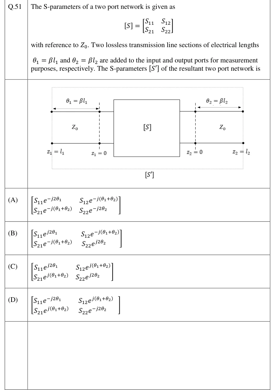 Tap to open full size
Figure description
A box labelled [S] in the centre (the original two-port). On its left, a two-wire transmission line section of characteristic impedance Z_0 is attached to port 1. Its outer (far-left) terminals are marked z_1 = l_1 and the terminals where it meets the [S] box are marked z_1 = 0 (dashed vertical reference line). A double-headed arrow above this left section is labelled theta_1 = beta l_1. On the right, a second two-wire line section of characteristic impedance Z_0 is attached to port 2. The terminals at the box are marked z_2 = 0 (dashed vertical reference line) and the outer (far-right) terminals are marked z_2 = l_2. A double-headed arrow above it is labelled theta_2 = beta l_2. A dotted rectangle encloses both line sections and the [S] box, and is labelled [S'] beneath it: the new two-port whose reference planes are at z_1 = l_1 and z_2 = l_2.
- (A)
- (B)
- (C)
- (D)