IAE Academy

GATE EE · IN

Instrument transformers

Instrument transformers, the current transformer (CT) and the potential or voltage transformer (PT), scale line currents and voltages down to standard instrument levels (commonly 5 A or 1 A, and 110 V) and isolate the instruments from the high-voltage circuit. The topic comes down to a few ideas: nominal versus actual ratio, ratio error and phase-angle error and what causes them, burden, why a CT secondary must never be opened (and a PT secondary never shorted), and how these errors carry into wattmeter and energy-meter readings.

3 previous-year questions · 3 solved · 6 practice questions

Ratios, ratio error and phase angle

A current transformer (CT) has its primary in series with the line, so the line current flows through it whatever the CT is feeding. Its secondary supplies ammeters and the current coils of wattmeters, energy meters and relays, all connected in series. A potential transformer (PT), also called a voltage transformer, has its primary connected across the line and supplies voltmeters and pressure coils connected in parallel. Both isolate the instruments from the high-voltage circuit and let standard low-range instruments serve any line rating.

Conventions on this page. Ratios are written primary : secondary (1000/5 A means 1000 A primary for 5 A secondary). All currents and voltages are rms magnitudes. Ratio error is a percentage of the true value. A lagging power-factor angle is positive. Phase angles are in radians inside formulas unless marked otherwise.

NOMINAL RATIO

Read off the rating plate and fixed for the transformer. For example, 1000/5 A gives and 11000/110 V gives . Readings are normally multiplied by .

ACTUAL RATIO (TRANSFORMATION RATIO)

The ratio of the actual primary magnitude to the actual secondary magnitude at the operating point. It is not constant: it changes with the primary current or voltage, the burden and the burden power factor.

TURNS RATIO

Both are defined so that . A bar (single-turn) primary CT has , so . With turns compensation, is made slightly smaller than .

RATIO CORRECTION FACTOR

An RCF above 1 means the nominal-ratio figure is too low. For an ideal transformer RCF = 1. In terms of RCF, ratio error .

RATIO ERROR (CURRENT ERROR OR VOLTAGE ERROR)

The error in the value obtained with the nominal ratio, as a percentage of the true value. Positive means reading is high and negative means it is low. For a PT, replace with . If the ratio error is (as a fraction), then .

Phase angle. For a CT this is the angle between the primary current and the reversed secondary current. For a PT it is the angle between the primary voltage and the reversed secondary voltage. (Drawn in the induced-emf sense, the secondary phasor sits nearly from the primary one, and reversing it brings it almost into line.) An ideal instrument transformer has zero phase angle. This page takes the phase angle as positive when the reversed secondary phasor leads the primary phasor. A phase angle quoted as 'x minutes lead' is therefore , and 'x minutes lag' is .

EXAM TIP

Ratio error affects every reading taken through the transformer. Phase angle affects only readings that depend on the phase between voltage and current: wattmeters, energy meters, power-factor meters and phase-sensitive relays. Phase angle has no effect on an ammeter fed from a CT or a voltmeter fed from a PT.

Current transformer: where the errors come from

In an ideal CT the primary ampere-turns would exactly balance the secondary ampere-turns. That would give , with the reversed secondary current exactly in phase with . A real core needs an exciting current (referred to the primary), which has two components. The magnetising component is in phase with the core flux. The core-loss component is in phase with the reversed induced emf, so it leads the flux by (the induced emf itself lags the flux by ). The primary current is the phasor sum of (the reversed secondary current referred to the primary) and . Because is not in phase with , part of it adds to the magnitude (the ratio error) and part of it adds in quadrature (the phase angle).

Symbols: is the phase angle of the whole secondary circuit (winding, leads and burden), that is, the angle by which lags the secondary induced emf, with . is the angle by which leads the flux, so and . , and are in primary amperes and is in secondary amperes. If the exciting requirement is given in ampere-turns, divide by . For a bar primary, ampere-turns equal amperes.

CT SECONDARY EMF AND CORE FLUX

is the impedance magnitude of the whole secondary circuit (winding, leads and burden); is the peak core flux, the peak flux density and the core cross-section, for sinusoidal flux at frequency . The flux the CT must carry, and so its exciting current, is set by and the burden impedance, which is why the core flux follows the line current.

CT ACTUAL RATIO

Valid when . Since , : the correction term is always positive, so . An uncompensated CT () therefore has and a negative ratio error, approximately , which means it reads low.

CT PHASE ANGLE

Positive (the reversed secondary current leads ) while , zero at and negative beyond. Here is the secondary current referred to the primary.

CT WITH A PURELY RESISTIVE SECONDARY CIRCUIT

Use this when the secondary circuit, winding included, is purely resistive. The loss component then sets the ratio error and the magnetising component sets the phase angle.

RADIANS TO DEGREES AND MINUTES

Instrument-transformer phase angles are small and are usually quoted in minutes of arc; rad.

EXAM TIP

How the CT errors move, read off the formulas above: (1) The CT must generate an emf , so a larger burden impedance at an unchanged burden power factor needs more flux and a larger , and both error terms, and , grow. (2) If the secondary circuit becomes more inductive (larger ) with unchanged, the ratio term grows (up to ) and the phase angle shrinks. The phase angle is zero at and negative beyond that. (3) At low primary current the core works at a low flux density, where its permeability is lower. So , and with it both errors, tends to be larger than at rated current.

Reducing CT errors

  1. Use a core of high permeability and low loss, worked at a low flux density, so that is small.

  2. Keep the magnetic path short and the core cross-section generous. A ring core with the secondary wound evenly around it reduces the exciting mmf and keeps leakage reactance low.

  3. Keep the burden in ohms, including the leads, low and within the rated burden.

  4. Turns compensation: make one or a few turns less than , so that at one chosen current and burden. This corrects only the ratio error; the phase angle is practically unchanged.

WORKED EXAMPLE

A 1000/5 A bar-primary CT has 200 secondary turns. At rated secondary current, the secondary circuit (winding plus burden) has a lagging phase angle with . The core needs a magnetising mmf of 4 AT and a core-loss mmf of 1.5 AT. Find (a) the actual ratio, (b) the ratio error, (c) the phase angle in minutes, and (d) the ratio error if the secondary is wound with 199 turns instead, taking the exciting mmf and as unchanged.

Solution
  1. Bar primary, so , and . Ampere-turns equal primary amperes, so A and A. Also , and A.

  2. (a) .

  3. (b) . The CT reads low.

  4. (c) rad . It is positive, so the reversed secondary current leads .

  5. (d) With : , so the ratio error . Removing one turn overshoots slightly but cuts the error magnitude from 0.359% to 0.140%. The phase angle is practically unchanged: rad .

Answer: (a) ; (b) ; (c) about , with the reversed secondary current leading; (d) .

Burden, and why a CT secondary is never opened

The burden is the load on the secondary: all the instruments plus the connecting leads. It is stated in volt-amperes, with its power factor, at rated secondary current for a CT or at rated secondary voltage for a PT. The rated burden is the VA, at a stated power factor, on which the transformer's accuracy class is based; its errors are guaranteed to stay within the class limits only if the actual burden does not exceed it.

BURDEN IN OHMS

The burden includes the leads. On a CT the instruments are in series, so their impedances add. On a PT they are in parallel, so their admittances add. Examples: 15 VA on a 5 A CT is 0.6 Ω, 15 VA on a 1 A CT is 15 Ω, and 100 VA on a 110 V PT is 121 Ω.

EXAM TIP

'More burden' means opposite things for the two transformers. For a CT, a larger burden is a larger secondary impedance in ohms (more instruments in series, longer leads). For a PT, a larger burden is a smaller impedance that draws more VA (more instruments in parallel). Either way the burden drives the errors: on a CT a larger burden raises the exciting current and both error terms; on a PT the ratio and the phase angle shift almost linearly with burden VA at a fixed power factor. A 1 A CT secondary copes with long leads better than a 5 A one, because the same lead resistance consumes only of the VA.

In normal service the CT's secondary ampere-turns almost cancel its primary ampere-turns, so the core works at a low flux density. The primary current is set by the load on the line, not by the CT. If the secondary is opened, nothing opposes the primary mmf and the whole primary current becomes exciting current. The core is driven deep into saturation and the flux becomes flat-topped. Its rapid reversals near each current zero induce very high peak voltages across the open secondary, which endanger both personnel and insulation. Core loss also rises sharply and overheats the core. Afterwards the core may keep some residual magnetism, which changes its ratio and phase-angle errors.

Safe practice with CT secondaries

  1. Keep the secondary closed, either through its burden or through a short circuit, whenever the primary may carry current.

  2. Close the shorting switch or link across the secondary terminals before removing or changing an instrument. Open it only after the new circuit is complete.

  3. Never fuse a CT secondary, because a blown fuse is an open circuit.

  4. Earth one point of the secondary circuit, so that an insulation failure cannot put line voltage on the instruments.

  5. If a secondary has been opened while the primary carried current, demagnetise the core before relying on its accuracy again.

Potential transformer: ratio and phase-angle error

A PT is a precision step-down transformer that works close to no load, because its burden is made up of high-impedance voltmeters and pressure coils. Its errors come from voltage drops: the exciting current flowing through the primary winding impedance, and the load current flowing through both windings. The derivation follows the one for transformer regulation, resolving each drop into components in phase with and in quadrature to the reversed secondary voltage.

Symbols: . and are the resistance and leakage reactance of the primary and secondary windings. and are the totals referred to the primary. is the burden phase angle, the angle by which lags . and are the loss and magnetising components of the exciting current, in primary amperes; if the no-load current is given with its power factor , then and .

PT ACTUAL RATIO

Valid when the winding drops are small compared with (the normal case), so the exciting-current components can be taken in phase with and in quadrature to the reversed secondary voltage. At no load () this becomes . The load term is proportional to , so for a burden of fixed power factor the ratio, and hence the ratio error, changes almost linearly with the burden VA.

PT PHASE ANGLE

Sign as on this page: positive when the reversed secondary voltage leads . At no load it is . The load term is negative whenever , and in that case adding burden swings the reversed secondary voltage towards lagging . Setting gives the burden at which the phase angle vanishes; for a unity-power-factor burden () that is .

WORKED EXAMPLE

A 6600/110 V PT is uncompensated, with . Its primary winding has Ω and Ω, and the totals referred to the primary are Ω and Ω. The no-load current is 0.005 A at a power factor of 0.4. With the secondary at 110 V, find (a) the ratio error and phase angle at no load, (b) the unity-power-factor burden, in VA, at which the phase angle is zero, and (c) the ratio error at that burden.

Solution
  1. . A and A.

  2. (a) , so the ratio error . Phase angle: rad , positive, so the reversed secondary voltage leads .

  3. (b) With the load term is . Zero phase angle needs , so A and the burden VA.

  4. (c) The load drop in phase is V, so and the ratio error .

Answer: (a) and about (reversed secondary voltage leading); (b) about 10.7 VA; (c) .

EXAM TIP

Turns compensation for a PT: with a resistive or lagging burden, exceeds by the drop terms, so is made slightly less than , by removing a few primary turns or adding a few secondary turns, so that at a chosen burden. A PT secondary must never be short-circuited: it is a voltage source, and a short would drive a very large current through the windings. PT circuits are therefore protected by fuses, whereas CT secondaries never are.

CT and PT side by side

Feature

Current transformer (CT)

Potential transformer (PT)

Primary connection

In series with the line

Across the line

What sets the primary quantity

The line (load) current, independent of the CT burden

The line voltage

Normal operating condition

Secondary nearly short-circuited (low-impedance burden)

Secondary nearly open-circuited (high-impedance burden)

Core flux in service

Low; rises and falls with the line current

Nearly constant at a given line voltage

Typical rated secondary

5 A or 1 A

110 V (or V per phase)

Instruments on the secondary

In series: ammeter, current coils

In parallel: voltmeter, pressure coils

Turns ratio

Burden in ohms

; more burden means more ohms

; more burden means fewer ohms

Main source of error

Exciting current compared with

Winding drops caused by load and exciting current

Dangerous secondary condition

Open circuit

Short circuit

Secondary protection

Shorting switch; never a fuse

Fuse

Turns compensation

Fewer secondary turns

Fewer primary turns or more secondary turns

Wattmeters and energy meters fed through a CT and a PT

On a high-voltage circuit, a wattmeter (or energy meter) has its current coil on the CT and its pressure coil on the PT. Neglecting the wattmeter's own errors, it responds to , where is the angle between the reversed secondary voltage and the reversed secondary current. The ratio errors scale and , and the phase angles rotate them, so differs from the load angle . The power is normally worked out as using the nominal ratios; finding the true power needs the actual ratios and the true angle. With a CT alone (low-voltage metering), set and use the line voltage directly.

ANGLE SEEN BY THE WATTMETER

is positive for a lagging load. and are positive when the reversed secondary phasor leads its primary. A leading CT phase angle makes a lagging load look closer to unity power factor.

TRUE POWER FROM THE WATTMETER READING

and are the actual PT and CT ratios at the operating point. The same factors multiply the energy registered by an energy meter. If ratio errors are neglected, replace with .

ERROR OF THE NOMINAL-RATIO POWER (SMALL ERRORS)

. Here and are the PT and CT ratio errors in percent, and the phase angles are in radians. Valid while the ratio errors are small and ; for a leading load , and so , is negative. Because of the factor, phase-angle errors are negligible near unity power factor and large at low power factor.

WORKED EXAMPLE

A single-phase load on a nominally 6.6 kV line is metered through a PT of nominal ratio 6600/110 V and a CT of nominal ratio 100/5 A. At the operating point the PT has a ratio error of and a phase angle of 20' lag (the reversed secondary voltage lags ). The CT has a ratio error of and a phase angle of 30' lead (the reversed secondary current leads ). The secondary instruments read 110 V, 5 A and 440 W, and the load power factor is lagging. Find the true power and power factor, and the error in the power computed with the nominal ratios.

Solution
  1. Meter angle: , so .

  2. Phase angles on this page's convention: and . From : , so the true power factor is lagging.

  3. Actual ratios from : and .

  4. True power: kW.

  5. Nominal-ratio figure: kW. This is high. Check with the small-error shortcut: , using rad and .

Answer: True power ≈ 522.7 kW at a power factor of 0.791 lagging. The nominal-ratio value of 528.0 kW is about 1.0% high.

EXAM TIP

Work with the phasors as well as the formula. If a question words the angles differently (for example 'the secondary current lags'), sketch each reversed secondary phasor relative to its primary and read off directly. Remember too that a CT with a positive phase angle makes a wattmeter read high on lagging loads and low on leading loads.

PREVIOUS-YEAR QUESTIONS

3 questions from the EE and IN papers

Try each question first, then open the answer. We placed each question under a topic ourselves; the exam paper does not label topics.

See these papers in full: GATE EE 2024 · GATE IN 2024 · GATE IN 2020

GATE 2024 EE Q.23

GATE 2024 · EEQ.23 · 1 mark · MCQ

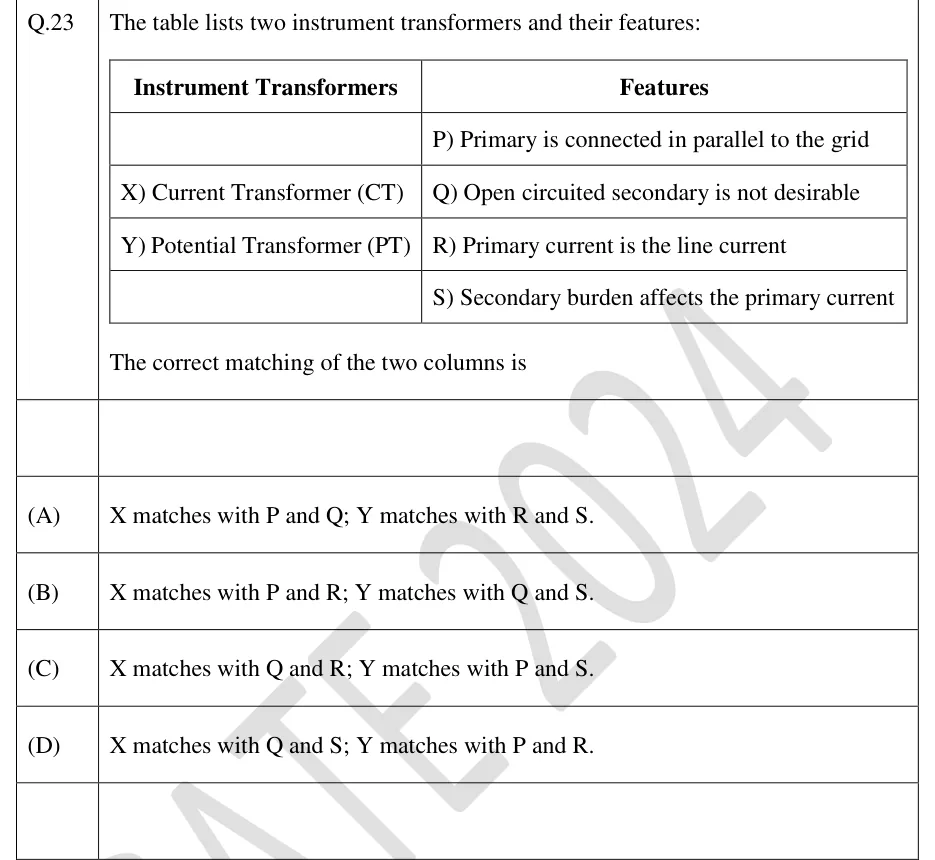
The table lists two instrument transformers and their features:

| Instrument Transformers | Features |
|---|---|
| | P) Primary is connected in parallel to the grid |
| X) Current Transformer (CT) | Q) Open circuited secondary is not desirable |
| Y) Potential Transformer (PT) | R) Primary current is the line current |
| | S) Secondary burden affects the primary current |

The correct matching of the two columns is

  1. (A)

    X matches with P and Q; Y matches with R and S.

  2. (B)

    X matches with P and R; Y matches with Q and S.

  3. (C)

    X matches with Q and R; Y matches with P and S.

  4. (D)

    X matches with Q and S; Y matches with P and R.
Answer and solution
See the question in the paper
GATE 2024 EE Q.23: answer and solution

GATE 2024 IN Q.47

GATE 2024 · INQ.47 · 2 marks · MCQ

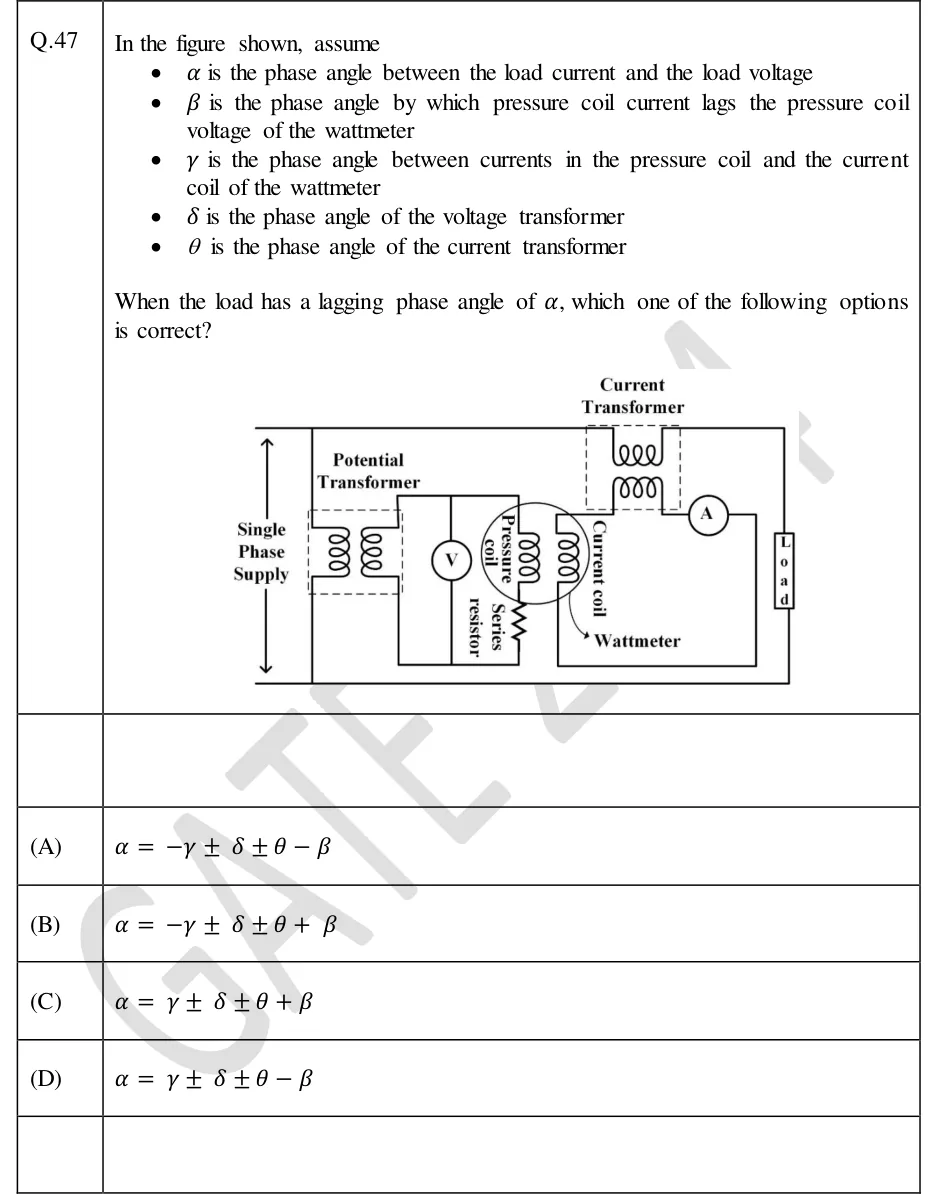
In the figure shown, assume

  • is the phase angle between the load current and the load voltage
  • is the phase angle by which pressure coil current lags the pressure coil voltage of the wattmeter
  • is the phase angle between currents in the pressure coil and the current coil of the wattmeter
  • is the phase angle of the voltage transformer
  • is the phase angle of the current transformer

When the load has a lagging phase angle of , which one of the following options is correct?

GATE 2024 IN question 47: A single-phase supply (vertical double-headed arrow labelled 'Single Phase Supply') on the left, with a top line and a…Tap to open full size
Figure from the GATE 2024 IN paper. It is part of the question.
Figure description

A single-phase supply (vertical double-headed arrow labelled 'Single Phase Supply') on the left, with a top line and a bottom line. The top line runs right through the primary winding of a 'Current Transformer' (CT, drawn in a dashed box at the top) to a load (box labelled 'Load') on the far right; the load returns to the bottom line. The primary of a 'Potential Transformer' (PT, dashed box) is connected across the supply. The PT secondary feeds a voltmeter V and, in parallel with it, the wattmeter's pressure coil in series with a 'Series resistor'. The CT secondary feeds an ammeter A in series with the wattmeter's current coil. The wattmeter (circle enclosing the pressure coil and current coil) is labelled 'Wattmeter'. So the voltmeter and pressure coil see the PT secondary voltage, and the ammeter and current coil carry the CT secondary current.

  1. (A)

  2. (B)

  3. (C)

  4. (D)

Answer and solution
GATE 2024 IN Q.47: answer and solution

GATE 2020 IN Q.52

GATE 2020 · INQ.52 · 2 marks · NAT

A 1000/1 A, 5 VA, UPF bar-primary measuring current transformer has 1000 secondary turns. The current transformer exhibits a ratio error of and a phase error of 3.438 minutes when the primary current is 1000 A. At this operating condition, the rms value of the magnetization current of the current transformer (in amperes, rounded off to two decimal places) is ____

Answer and solution
See the question in the paper
GATE 2020 IN Q.52: answer and solution

PRACTICE

6 questions to test yourself

PRACTICE 11 mark · NAT

A CT with a rated secondary current of 5 A has a rated burden of 12.5 VA. Its secondary supplies an ammeter of 0.12 Ω and a wattmeter current coil of 0.08 Ω, connected in series through leads. All of these are effectively resistive. The maximum total lead resistance, in ohms, that keeps the burden within its rating at rated current is ____.

Answer and solution

Answer: (accepted range )

  1. Rated burden in ohms: Ω.

  2. The instruments are in series: Ω.

  3. Maximum lead resistance Ω.

PRACTICE 22 marks · MSQ

Which of the following statements about instrument transformers are correct?

  1. (A)

    For an uncompensated CT, increasing the burden impedance (in ohms) connected to the secondary, at an unchanged burden power factor, increases the magnitudes of its ratio error and phase angle.

  2. (B)

    Connecting more instruments in parallel across a PT secondary reduces the burden on the PT.

  3. (C)

    A PT of nominal ratio 3300/110 V whose secondary reads 109.5 V when its primary is at exactly 3300 V has a negative ratio error, with ratio error defined as .

  4. (D)

    A fuse should be connected in the CT secondary circuit to protect the instruments.

Answer and solution

Answer: (A), (C)

  1. A: correct. A larger burden impedance needs a larger secondary emf , so more flux and a larger exciting current are needed. With unchanged, both and grow.

  2. B: wrong. Instruments in parallel lower the impedance and draw more VA, which increases the burden.

  3. C: correct. , so .

  4. D: wrong. A blown fuse would open-circuit the CT secondary, which is the one condition that must never occur.

PRACTICE 32 marks · NAT

A wattmeter is connected through a CT of nominal ratio 50/5 A and a PT of nominal ratio 1100/110 V. Take both ratio errors as zero. At the operating point the reversed CT secondary current leads the primary current by 40 minutes, and the reversed PT secondary voltage leads the primary voltage by 10 minutes. The load power factor is 0.5 lagging. The power obtained as (nominal ratios × wattmeter reading) exceeds the true power by ____ percent (round off to two decimal places).

Answer and solution

Answer: (accepted range )

  1. lagging; and .

  2. .

  3. With zero ratio errors, measured/true , so the measured power is high.

  4. Shortcut check: .

PRACTICE 42 marks · NAT

A 3300/110 V potential transformer is uncompensated, with turns ratio . Its primary winding has resistance 300 Ω and leakage reactance 250 Ω; the totals referred to the primary are 600 Ω and 500 Ω. The no-load current is 0.02 A at a power factor of 0.3. Using the standard approximate PT phase-angle equation, the unity-power-factor burden, in VA at a secondary voltage of 110 V, at which the phase angle is zero is ____ (round off to one decimal place).

Answer and solution

Answer: (accepted range )

  1. A and A.

  2. No-load phase-angle numerator: V (positive, so the reversed secondary voltage leads at no load).

  3. With a unity-power-factor burden () the load term is , so zero phase angle needs , giving A.

  4. Burden VA. The 600 Ω total resistance does not enter, because .

PRACTICE 51 mark · MCQ

The secondary of a current transformer is open-circuited while its primary carries rated line current. Which statement best describes what happens?

  1. (A)

    The primary current rises sharply because the CT no longer limits it.

  2. (B)

    The whole primary mmf becomes exciting mmf, the core saturates, and a dangerously high peak voltage appears across the secondary terminals.

  3. (C)

    A very large current flows in the secondary winding and overheats it.

  4. (D)

    The ratio error becomes zero and the phase angle becomes .

Answer and solution

Answer: (B)

  1. The primary current is set by the load on the line, not by the CT, so it does not change. A is wrong.

  2. With the secondary open, no secondary ampere-turns oppose the primary, so all of the primary mmf magnetises the core. The core saturates, and the flux reverses rapidly near each current zero, inducing very high peak voltages in the many-turn secondary. B is correct.

  3. No current can flow in an open secondary, so C is wrong. D is wrong: with no secondary current the CT no longer transforms current at all, so ratio error and phase angle lose their meaning.

PRACTICE 62 marks · NAT

A bar-primary current transformer of nominal ratio 1000/5 A has 199 secondary turns. At rated secondary current the secondary circuit (winding plus burden) is purely resistive, and the core needs a magnetising mmf of 6 AT and a core-loss mmf of 3 AT. Use the standard approximate CT equations, with ratio error defined as . The ratio error, in percent, is ____ (round off to two decimal places).

Answer and solution

Answer: (accepted range )

  1. Bar primary: , so , and ampere-turns equal primary amperes, giving A and A.

  2. Purely resistive secondary (): .

  3. , so the ratio error .

  4. The magnetising mmf affects only the phase angle: rad.

OFFICIAL GATE 2027 SYLLABUS WORDING

Copied from the GATE 2027 syllabus; see all 2027 syllabi.

GATE EE

Instrument transformers

GATE IN

instrument transformers

Preparing in Kolkata? IAE Academy's course for GATE EE or GATE IN.