IAE Academy

GATE EE · IN

Bridges, potentiometers and the Q-meter

Bridges and potentiometers are null methods. The unknown is read from the settings of known, stable components at the moment a detector shows zero, so the result does not depend on the detector's calibration. At balance the detector carries no current, and in a potentiometer this means no current is drawn from the source being measured. The core skill is writing the balance condition for the arm arrangement given ( for a DC bridge, in both magnitude and phase for an AC bridge) and separating real and imaginary parts, plus a short list of instrument-specific results: the Kelvin double bridge's link term, Hay's frequency-dependent term, the Q-meter's corrections for shunt resistance and self-capacitance, the loss-of-charge formula for megohm values, and potentiometer standardisation.

14 previous-year questions · 14 solved · 7 practice questions

DC bridges: Wheatstone and Kelvin double bridge

A common classification of resistances by measurement method: low (below about 1 Ω, e.g. ammeter shunts, cable conductors, contacts), medium (about 1 Ω to 100 kΩ) and high (above about 100 kΩ, e.g. insulation). The Wheatstone bridge covers the medium range. Below about 1 Ω the resistance of leads and contacts is comparable with the unknown, so a four-terminal method such as the Kelvin double bridge is needed. Above about 100 kΩ the galvanometer current becomes very small and surface leakage currents compete with it, so guarded methods are used.

Labelling used in this section: the supply is connected across A (positive) and C; the arms are AB , BC , AD (the unknown) and DC (the standard); the galvanometer, of resistance , connects B and D. and are the ratio arms. At balance B and D are at the same potential, so no current flows in the galvanometer.

WHEATSTONE BRIDGE BALANCE

Products of opposite arms are equal. The condition does not involve , or the source resistance, and it is unchanged if the supply and the galvanometer are interchanged (only the sensitivity changes).

LIMITING ERROR OF A WHEATSTONE MEASUREMENT

Limiting error is a guaranteed (worst-case) bound: for a product or quotient, the relative limiting errors of the factors add, whether a factor multiplies or divides. For example, arms each known to give to within . Any lack of detector sensitivity (the smallest unbalance that can be seen) adds to this.

UNBALANCED BRIDGE: THEVENIN EQUIVALENT AT THE GALVANOMETER TERMINALS

Open-circuit voltage of B with respect to D, and the resistance seen from B–D. This simple holds for a supply of negligible internal resistance; with a source resistance, find by a delta–star conversion instead.

GALVANOMETER CURRENT AND DEFLECTION

Current in a galvanometer of resistance connected across an unbalanced bridge. is the galvanometer's current sensitivity (e.g. mm/μA).

SMALL UNBALANCE, AND THE EQUAL-ARM BRIDGE

Change in the open-circuit output when the unknown moves from its balance value to , with for the approximate forms. For a given , is largest at , so equal arms give the largest open-circuit output per ohm of unbalance. The middle form is exact and shows the output is linear only for small .

BRIDGE SENSITIVITY

Deflection per unit fractional change in the unknown (divide by 100 for deflection per 1% change). It rises with the supply voltage and with a more sensitive galvanometer; the supply is limited by the heating the arms can tolerate.

QUARTER, HALF AND FULL BRIDGES (EQUAL ARMS $R$, SUPPLY $E$)

Open-circuit output with one, two or four active arms (e.g. strain gauges), each changing by . The active arms must be placed so their effects add: two adjacent arms must change in opposite senses, two opposite arms in the same sense. The full bridge, and the half bridge with two adjacent arms changing in opposite senses, are exactly linear. The quarter bridge, and a half bridge with two opposite arms changing in the same sense (exact output ), are linear only for small .

Limitations of the Wheatstone bridge

  1. Low resistances: the resistance of connecting leads and contacts adds directly to the unknown arm and can be comparable with it.

  2. Thermo-electric emfs at junctions of dissimilar metals add a small DC offset; reverse the supply, rebalance, and average the two readings.

  3. High resistances: the galvanometer current becomes too small to show a clear null, and leakage currents over insulating surfaces flow in parallel with the unknown.

  4. Heating: arm currents must be small enough that heating does not change the resistances being measured.

EXAM TIP

Lead compensation in a resistance-thermometer bridge (three-wire connection): one lead of resistance is placed in the sensor's arm and an identical lead in the adjacent arm , and the third lead carries the detector connection. Balance then gives , so with the leads cancel exactly: .

For low resistances the unknown and the standard are made four-terminal resistors. Current enters and leaves by one pair of terminals, and the resistance is defined between a separate pair of potential terminals, so the current-lead and contact resistances lie outside the measured section. What remains is the link, of resistance , joining the current terminals of and . If the galvanometer could be connected to a point that divides into (on the side) and with , balance would give , which reduces exactly to . The Kelvin double bridge locates that point electrically with a second pair of ratio arms and connected across the link, their junction going to the galvanometer.

KELVIN DOUBLE BRIDGE BALANCE

= outer ratio arms; = inner ratio arms ( and on the side of the unknown , and on the side of the standard ); = resistance of the link between and . The second term is the error caused by the link, and it has the sign of .

KELVIN DOUBLE BRIDGE WITH MATCHED RATIOS

In practice the two ratio pairs are ganged so they stay equal, the link is made short and thick so any residual mismatch multiplies a small , and every ratio arm is made much larger than the lead and contact resistances in series with it. Used for resistances below about 1 Ω, such as shunts and busbar sections.

WORKED EXAMPLE

A Wheatstone bridge has and is balanced when the unknown . The supply is 10 V with negligible internal resistance, and the galvanometer has resistance and current sensitivity 1 mm/μA. The unknown rises to . Find the galvanometer current, the deflection and the bridge sensitivity, and compare the current with the small-unbalance approximation.

Solution
  1. mV.

  2. .

  3. .

  4. Deflection mm.

  5. , so mm per unit fractional change, i.e. about 41.4 mm for a 1% change.

  6. Approximation: mV and , giving A, within 1% of the exact value.

Answer: A (41.7 μA by the approximation); deflection about 41.4 mm; mm per unit fractional change.

WORKED EXAMPLE

A Kelvin double bridge has outer ratio arms , and inner ratio arms , (a small mismatch). The standard is and the link resistance is . Find the unknown at balance and the error made by using . Repeat for .

Solution
  1. Main term: mΩ.

  2. Ratio mismatch: .

  3. Link factor: .

  4. Correction mΩ, so mΩ. Using alone would read about 8.3% low.

  5. With the link factor is , the correction is 0.0091 mΩ and mΩ; ignoring the link term now costs only about 0.9%.

Answer: mΩ with (8.3% error if the link term is ignored); mΩ with (0.9% error). Matching the ratios removes the error; a low-resistance link shrinks whatever mismatch remains.

EXAM TIP

In the Kelvin formula, if the outer ratio exceeds the inner ratio , the true is larger than , and vice versa. The multiplier is almost exactly because the link is tiny compared with the inner arms.

High resistance (megohm) measurement

At high resistance the current through the specimen is tiny, and the current that leaks over the surface of the insulation (and through its supports) can be as large as the current through its volume. An insulating specimen therefore has a volume resistance and a surface resistance in parallel, and a measurement must say which one it reports. High resistances are measured at high test voltages (hundreds to thousands of volts) to obtain a readable current, and with a guard that routes unwanted leakage away from the meter or detector.

A guard is a conductor placed on the leakage path and held at (nearly) the same potential as the measuring terminal it protects. With almost no voltage between them, almost no current flows from that terminal to the guard. Surface leakage is intercepted by the guard and returned to the supply without passing through the meter. With a guard ring around the measuring electrode of a sheet or cable sample, the meter reads only the volume current.

DIRECT-DEFLECTION METHOD

Test voltage and galvanometer (or electrometer) current . With the guard connected the result is the volume resistance; without it, the parallel combination of volume and surface resistance.

LOSS-OF-CHARGE METHOD

A capacitor charged to discharges through the unknown ; is the voltage after time , read on a voltmeter that draws no current (an electrostatic voltmeter). It suits very high resistances, where the decay is slow enough to time accurately; with a small the voltage collapses too quickly.

LOSS OF CHARGE: CORRECTING FOR THE CAPACITOR'S OWN LEAKAGE

is the leakage resistance of the capacitor itself (together with that of the voltmeter), found by a second test with disconnected. It is always in parallel with , so the first test gives .

A megohm bridge is a Wheatstone bridge built for high resistance, with a high-voltage supply, a sensitive detector and a guard terminal. The unknown is treated as a three-terminal resistor: its two main terminals plus a guard, and the guard is connected to the junction of the two ratio arms. One leakage path (from a main terminal to the guard) then lies across a ratio arm, whose resistance is far lower, so it changes that arm negligibly. The other leakage path lies across the detector, which has no voltage across it at balance and so carries no leakage current; it only lowers the detector's sensitivity slightly.

An insulation-resistance tester is a portable ohmmeter with its own high-voltage DC source (a hand-driven generator or an electronic converter). Its moving system is a ratio (crossed-coil) type with no control spring: one coil carries a current set by the test voltage, the other the current through the insulation, and the pointer settles where their torques balance. Because the reading depends on the ratio of the two currents, it is largely independent of the exact generator voltage. It reads infinity with the test terminals open and zero with them shorted, and its guard terminal removes surface leakage from the reading.

EXAM TIP

Leakage is always a parallel path, so an unguarded measurement of a high resistance reads low, never high.

EXAM TIP

In the loss-of-charge formula, is initial over final voltage (greater than 1), with in seconds and in farads. Halving the voltage takes .

AC bridges: the general balance condition

An AC bridge has the same four-arm ring as the Wheatstone bridge, with impedances to , an AC source across one diagonal and a detector across the other. Here is opposite , and is opposite . For a null, the detector's two terminals must be at the same potential in both magnitude and phase. The balance equation is therefore complex and gives two real conditions, so an AC bridge always needs two independent adjustments.

GENERAL AC BRIDGE BALANCE

Products of the impedances of opposite arms are equal. The admittance form is convenient when arms are parallel combinations.

MAGNITUDE AND PHASE CONDITIONS

Both must hold at once. is the impedance angle: positive for an inductive arm, negative for a capacitive arm, zero for a pure resistance.

Solving any AC bridge

  1. Write each arm's impedance: series elements as or , parallel elements as an admittance such as .

  2. Isolate the unknown: , or when the arm opposite the unknown is a parallel combination (this avoids dividing by a complex number).

  3. Expand, then equate real parts and imaginary parts separately: one equation gives the unknown's resistance (or loss), the other its reactance.

  4. Check whether survives in the result. If it does, the balance is frequency-dependent: the source frequency must be known and the source must be a clean sinusoid, because each harmonic would need a different balance.

EXAM TIP

Feasibility check from the phase condition: if two adjacent arms are pure resistances, the other two arms must both be inductive or both capacitive (with equal angles); if two opposite arms are pure resistances, the other pair must be one inductive and one capacitive (with equal and opposite angles). This is why a coil is balanced against a capacitive arm placed opposite it in the Maxwell–Wien and Hay bridges.

Q OF A COIL AND DISSIPATION FACTOR OF A CAPACITOR

Subscript = series equivalent circuit, = parallel equivalent circuit; in the parallel model the coil's . is the loss angle: minus the angle by which the capacitor's current leads its voltage. For small the capacitor's power factor . For a coil, . From here on denotes a quality factor, not a ratio arm of the DC bridges.

SERIES–PARALLEL EQUIVALENTS AT ONE FREQUENCY

Converts between the series model (natural for an arm like ) and the parallel model. For , and agree within 1%; for small , .

Detectors and sources. At power frequencies the classical null detector is a vibration galvanometer tuned to the supply frequency; at audio frequencies, headphones; in modern bridges, a tuned amplifier or an electronic null detector. Because the null is sought at one frequency, the source should be a clean sinusoid, and a tuned detector helps when it is not. Stray capacitance from the arms and the detector to earth adds unwanted admittance across the arms; it is controlled by screening the arms and by an auxiliary earthing arm (the Wagner earth) adjusted so that both detector terminals are at earth potential at balance.

EXAM TIP

Sliding balance (poor convergence): when one adjustable element appears in both balance equations, every adjustment disturbs the other condition, and the null is approached only slowly by alternating between the two controls. Convergence is fastest when each condition has its own adjusting element that appears in no other equation.

Inductance bridges: Maxwell, Maxwell–Wien, Hay and Anderson

Labelling for this section: the unknown coil, of inductance and resistance , is arm 1, . Arm 4 is opposite it. Arms 2 and 3 are the two arms adjacent to it and, except in the inductance-comparison bridge, are non-inductive resistors and .

MAXWELL INDUCTANCE (COMPARISON) BRIDGE

Arm 2 is a variable standard inductor with total series resistance (its own resistance plus any added resistor); arms 3 and 4 are resistors, opposite the unknown and opposite the standard. From . Frequency-independent; its drawback is the need for a variable standard inductor.

MAXWELL–WIEN (MAXWELL INDUCTANCE–CAPACITANCE) BRIDGE

Arm 4 = in parallel with a standard capacitor . From . The balance equations are free of frequency, and if and are the adjusted elements the two conditions are independent. Suited to medium-Q coils (roughly ).

HAY'S BRIDGE

Arm 4 = in series with . From . Both and depend on , so the frequency must be known. Suited to high-Q coils ().

HAY'S BRIDGE IN TERMS OF Q

Because . The approximation overstates by the factor : 1% at , 0.25% at . Use the exact form when a question gives and all the element values.

Why each bridge has a Q range. The phase condition makes arm 4's angle equal to , and a high-Q coil has close to . In the Maxwell–Wien bridge this needs , an impractically large resistor when is high. In Hay's bridge it needs , which is small and practical. At the other end, variable standard capacitors are costly, so is usually fixed and or is adjusted for the inductance balance instead. Then appears in both balance equations, and a low-Q coil () suffers a sliding balance.

The Anderson bridge is a modification of the Maxwell–Wien bridge that measures inductance in terms of a fixed capacitor, over a wide range of including low-Q coils. With the supply across nodes a and c: the coil (, total arm resistance ) is in arm ab and in bc; is in ad and in dc; from d a resistor goes to a fifth node e, and the capacitor goes from e to c. The detector connects b and e.

ANDERSON BRIDGE

Topology as described above: the series – branch is in parallel with , and the detector taps its midpoint. is the total resistance of the coil's arm: if a variable resistor is added in series with a coil of resistance to obtain balance, . The balance is frequency-independent, and does not appear in the resistance condition.

Anderson bridge: advantages and drawbacks

  1. Easy convergence: the resistance balance does not involve , so it is made first, and the inductance balance is then made with alone.

  2. The resistance balance can even be made with a DC supply and galvanometer: at DC the capacitor blocks, so at a null no current flows in , e is at the potential of d, and the balance reduces to .

  3. A fixed standard capacitor is used, so no variable standard capacitor is needed, and low-Q coils can be measured.

  4. Drawback: more components and an extra junction make the balance equations longer and the bridge harder to screen against stray capacitance.

Inductance bridges at a glance

Bridge

Arm opposite the coil

Result

Frequency in balance?

Best for

Maxwell inductance

(standard inductor in an adjacent arm)

No

Comparison with a variable standard inductor

Maxwell–Wien

,

No

Medium Q (roughly 1 to 10)

Hay

in series with

,

Yes

High Q (above 10)

Anderson

, shunted by in series with a fixed (detector at the – junction)

No

Wide Q range including low Q; precise work

WORKED EXAMPLE

An Anderson bridge (topology as above) balances with , , , and F, with no extra resistor in the coil's arm. Find the coil's inductance and resistance and its Q at 1 kHz. What settings would balance the same coil in a Maxwell–Wien bridge with and ?

Solution
  1. .

  2. .

  3. H.

  4. .

  5. Maxwell–Wien: F and . Check: , the same Q.

Answer: H, , at 1 kHz; Maxwell–Wien settings F and .

EXAM TIP

Identify the bridge from the arm opposite the coil: capacitor in parallel with a resistor = Maxwell–Wien; capacitor in series with a resistor = Hay. The two differ only in that arm, and swapping their formulas is a common slip.

EXAM TIP

The coil's Q is read from arm 4 alone: in the Maxwell–Wien bridge and its reciprocal in Hay's bridge. Neither depends on or .

Capacitance and frequency bridges: Schering and Wien

A real capacitor has dielectric loss, modelled as a series resistance (or an equivalent parallel resistance). A plain comparison bridge (the De Sauty bridge), with the unknown opposite a resistor and a loss-free standard opposite a resistor , balances only if and the unknown is loss-free: nothing in it can cancel a loss angle. The Schering bridge adds a capacitor across to do exactly that.

Schering bridge arms: arm 1 = capacitor under test, series model with ; arm 2 (adjacent to arm 1) = loss-free standard capacitor (air or gas dielectric); arm 3 (adjacent to arm 1, opposite arm 2) = non-inductive resistor ; arm 4 (opposite arm 1) = non-inductive resistor in parallel with a variable capacitor .

SCHERING BRIDGE BALANCE

From . Both equations are free of frequency. , the resistor in the arm opposite the unknown, is in the numerator for .

SCHERING BRIDGE DISSIPATION FACTOR

Series-model dissipation factor of the unknown; unlike and , it contains . With fixed, the dial can be calibrated directly in at one frequency, and is varied for the balance.

In a high-voltage Schering bridge (testing cables, bushings and insulating materials) the high voltage is applied at the junction of and , and the junction of and is earthed. The capacitive arms have far higher impedance than the resistive arms, so almost all of the test voltage appears across and , while , , and the detector stay close to earth potential, where the operator adjusts them. Spark gaps across and protect the low-voltage side if a specimen breaks down. The relative permittivity of a sample follows from two measurements of the test capacitor, with and without the sample: .

The Wien bridge places a series RC arm next to a parallel RC arm. Arm 1: in series with . Arm 2 (adjacent): in parallel with . The other two arms are resistors: , opposite arm 2 (it shares a node with the series-RC arm), and , opposite arm 1 (it shares a node with the parallel-RC arm). The balance condition does not depend on which diagonal carries the supply; in the usual drawing the series-RC and parallel-RC arms form one branch across the supply and , the other, with on the same supply terminal as the series-RC arm. Balance, , gives one real and one imaginary condition, and the imaginary one fixes the frequency.

WIEN BRIDGE BALANCE FREQUENCY

From the imaginary part of : .

WIEN BRIDGE RESISTANCE-RATIO CONDITION

Real part of the same equation. is the resistor opposite the parallel-RC arm, the one opposite the series-RC arm.

EQUAL-ELEMENT WIEN BRIDGE

With ganged and equal fixed capacitors, one dial reads frequency directly. At the series-RC/parallel-RC divider passes exactly one third of the voltage with zero phase shift, which is why a Wien-bridge oscillator's amplifier needs a gain of 3.

Uses and limitations of the Wien bridge

  1. Measuring audio frequencies, with the ganged resistors calibrated in hertz.

  2. Harmonic distortion analysis: tuned to the fundamental, the bridge nulls it and passes the harmonics, whose total can then be measured.

  3. The frequency-determining network of the Wien-bridge oscillator.

  4. Limitation: because the balance depends on frequency, a supply containing harmonics cannot be nulled completely, since only the fundamental balances. A filter or tuned detector is needed for a sharp null.

All the bridges in this topic

Bridge

Measures

Balance result

Frequency in balance?

Wheatstone

Medium R (about 1 Ω to 100 kΩ)

DC

Kelvin double

Low R (below about 1 Ω)

when

DC

Megohm (guarded Wheatstone)

High R

, guard at the ratio-arm junction

DC

Maxwell–Wien

L of medium-Q coils, in terms of C

,

No

Hay

L of high-Q coils

Yes

Anderson

L over a wide Q range, in terms of a fixed C

No

Schering

C and dissipation factor (insulation testing)

, ,

No (but contains )

Wien

Frequency; distortion analysis

Yes

EXAM TIP

Schering: , where is the resistor shunted by (opposite the unknown). A quick check from opposite-arm products in the loss-free case: .

EXAM TIP

The Schering bridge's has the same form as the Maxwell–Wien bridge's , because in both the arm opposite the unknown is . For the capacitor it is a dissipation factor, for the coil a quality factor.

The Q-meter

The Q-meter measures the quality factor of coils at radio frequencies, and by substitution their inductance and self-capacitance and the value of small capacitors, using series resonance. A variable-frequency oscillator drives a known current through a very small shunt resistance , injecting a small known voltage into a series loop formed by the coil under test and a calibrated variable tuning capacitor . An electronic voltmeter of very high input impedance reads the voltage across . The tuning capacitor (or the frequency) is adjusted for maximum reading, which is resonance, and because is fixed and known the voltmeter is calibrated directly in Q.

Q-METER PRINCIPLE

At resonance the loop's reactances cancel, so the current is ( = coil resistance) and the capacitor voltage is times the injected voltage. Assumes and the capacitor's losses are negligible compared with , the voltmeter does not load the circuit, and the self-capacitance is neglected.

INDUCTANCE FROM THE RESONANCE SETTING

= the coil's self (distributed) capacitance, which adds to the tuning capacitance as far as the resonant frequency is concerned. Neglect it only when .

CORRECTION FOR THE SHUNT (INSERTION) RESISTANCE

The shunt is part of the resonant loop, so the measured is slightly low. The correction is negligible when and matters for coils of very low resistance.

SELF-CAPACITANCE BY THE TWO-FREQUENCY METHOD

and are the tuning-capacitor settings for resonance at and at the higher frequency . From at both frequencies: .

CORRECTION FOR SELF-CAPACITANCE

is the reading taken at tuning setting . The self-capacitance acts across the coil's terminals, so the indicated Q falls short of the coil's true by the factor .

Measuring a capacitor by substitution

  1. Parallel method (unknown smaller than the largest tuning setting): resonate a working coil at a chosen frequency, with the tuning capacitor at and nothing else connected.

  2. Connect the unknown across the tuning capacitor and retune to resonance at the same frequency: the setting falls to .

  3. The total capacitance must be the same as before, so .

  4. Series method (larger capacitors; the coil's self-capacitance neglected): with the unknown inserted in series with the coil, the setting rises from to . The series combination of and must equal , so .

WORKED EXAMPLE

A coil tested on a Q-meter resonates at 500 kHz with the tuning capacitor at 400 pF, and at 1 MHz with it at 94 pF. At 500 kHz the meter indicates Q = 120. Neglecting the shunt resistance, find the self-capacitance, the inductance, the true Q at 500 kHz and the coil's effective resistance there.

Solution
  1. , so pF.

  2. H.

  3. Check at the second frequency: MHz.

  4. .

  5. .

Answer: pF, H, true , and at 500 kHz.

EXAM TIP

Every correction raises Q. The shunt resistance, the coil's self-capacitance and voltmeter loading all make the indicated Q lower than the true Q, so a corrected value smaller than the reading means the correction has been inverted.

EXAM TIP

In the two-frequency method the higher frequency needs the smaller tuning setting. With , , where is the setting at the lower frequency; a negative result means the settings were swapped.

EXAM TIP

With resonance settings at several frequencies, plot the tuning setting against . Since , the points lie on a straight line of slope whose intercept on the axis is .

DC and AC potentiometers

A potentiometer measures a voltage by opposing it with a known, adjustable voltage produced by a working current in a precision resistance (a uniform slide wire, or decade dials plus a slide wire). At balance the galvanometer carries no current, so no current is drawn from the source being measured. The potentiometer therefore reads the source's emf, unaffected by lead or source resistance, and its accuracy rests on the standard cell and the resistance network rather than on a pointer scale.

Standardising and using a DC potentiometer

  1. Set up the working current from a stable battery through a rheostat.

  2. Set the dials (or slide contact) to the emf of a standard cell, about 1.0186 V for a saturated cadmium cell, and adjust the rheostat until the galvanometer shows a null with the standard cell connected. The dials now read volts directly.

  3. Switch to the unknown and adjust the dials, not the rheostat, for a null; read the voltage.

  4. Re-check the standardisation afterwards, since the working battery drifts.

SLIDE-WIRE COMPARISON

and are the balance lengths for the standard emf and the unknown at the same working current , on a uniform wire of resistance per unit length; is the potential gradient (volts per unit length).

EXTENDING THE RANGE: VOLT-RATIO BOX

A precision resistive divider presents to the potentiometer ( = ratio, e.g. 10 or 100) and is the potentiometer reading. Unlike the potentiometer itself, the divider draws current from the circuit under test.

CURRENT MEASUREMENT

The potentiometer reads the drop across a four-terminal standard resistor carrying the current. This is how ammeters are calibrated.

RESISTANCE BY COMPARISON

and a standard carry the same current in series, and the potentiometer reads the two drops in quick succession. Suitable for low resistances, because only the potential terminals are involved.

INTERNAL RESISTANCE OF A CELL

= balance length with the cell on open circuit (its emf); = balance length with a known resistor connected across the cell (its terminal voltage).

An AC potentiometer must match the unknown in both magnitude and phase. There is no AC standard cell, so it is standardised on DC through a transfer instrument: the working current is set on DC against the standard cell with an electrodynamometer or thermal ammeter in the circuit, then on AC the current is reset to the same reading (these instruments read rms and indicate the same on AC and DC). The potentiometer must be supplied from the same source as the voltage being measured, so that both have the same frequency and a fixed phase relation, and the waveform must be sinusoidal, because harmonics cannot all be balanced at once. The detector is a vibration galvanometer or a tuned detector.

Two constructions are used. The polar type reads the magnitude on a slide wire and the phase angle on a calibrated phase-shifting transformer. The coordinate type has two slide wires, one carrying a current in phase with the supply and the other a current in quadrature with it (obtained through a mutual inductor); they read the in-phase and quadrature components of the unknown.

COORDINATE-TYPE AC POTENTIOMETER

= in-phase component, = quadrature component, both measured against the potentiometer's reference phase; the signs of and fix the quadrant of . The polar type gives and directly.

COIL IMPEDANCE WITH AN AC POTENTIOMETER

The coil and a non-inductive standard resistor carry the same current; and are the phasor voltages across them, measured against the same reference. The drop across is in phase with the current, which is what separates the coil's resistance from its reactance.

Applications of potentiometers

  1. Calibrating voltmeters (with a volt-ratio box), ammeters (with a standard resistor) and wattmeters (with both).

  2. Measuring emf, and low resistance by comparison with a standard.

  3. AC potentiometers: measuring self-inductance and coil parameters, magnetic testing, and the ratio and phase-angle errors of instrument transformers.

WORKED EXAMPLE

A DC potentiometer is standardised against a 1.0186 V standard cell. (a) A voltmeter reading 150 V is checked through a 100:1 volt-ratio box, and the potentiometer balances at 1.4935 V. (b) An ammeter reading 5.00 A is checked with a standard resistor in series with it, and the potentiometer balances at 0.4985 V across the resistor. Find the error of each instrument as a percentage of the true value.

Solution
  1. True voltage V.

  2. Voltmeter error reading true V, i.e. (the meter reads high). The correction to apply to its reading is V.

  3. True current A.

  4. Ammeter error A, i.e. .

Answer: Voltmeter (reads 0.65 V high); ammeter (reads 0.015 A high); both as a percentage of the true value.

EXAM TIP

A potentiometer measures emf, an open-circuit quantity; a voltmeter across the same cell reads the lower terminal voltage because it draws current. The volt-ratio box is the one part of a potentiometer set-up that does load the circuit.

EXAM TIP

Standardisation fixes the working current. Once standardised, adjust only the measuring dials: touching the rheostat afterwards invalidates every reading until the potentiometer is standardised again.

EXAM TIP

Error convention: error = measured true (positive when the instrument reads high) and correction = true measured. Percentages are of the true value unless a question says of full scale.

PREVIOUS-YEAR QUESTIONS

14 questions from the EE and IN papers

Try each question first, then open the answer. We placed each question under a topic ourselves; the exam paper does not label topics.

See these papers in full: GATE EE 2026 · GATE EE 2025 · GATE IN 2026 · GATE IN 2025 · GATE IN 2024 · GATE IN 2023 · GATE IN 2022 · GATE IN 2020 · GATE IN 2018

GATE 2026 EE Q.57

GATE 2026 · EEQ.57 · 2 marks · NAT

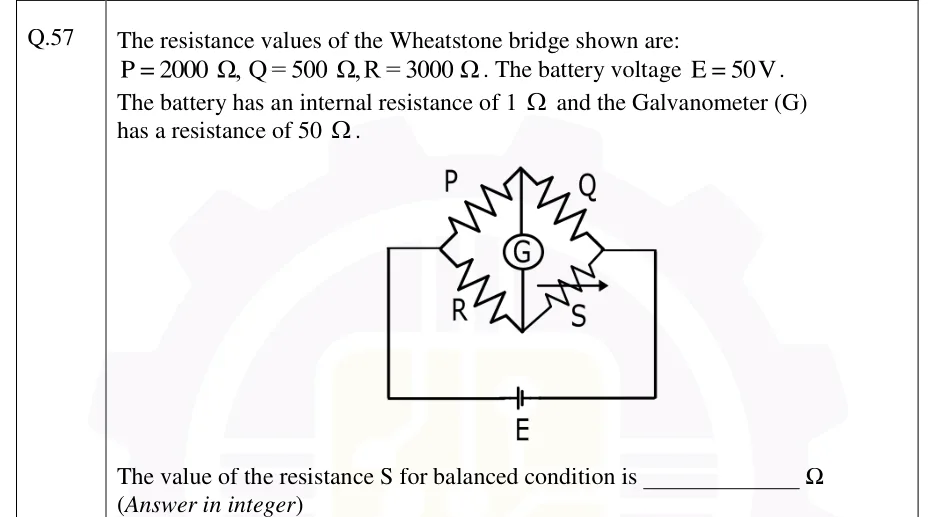
The resistance values of the Wheatstone bridge shown are: , , . The battery voltage . The battery has an internal resistance of and the Galvanometer (G) has a resistance of .

[Figure]

The value of the resistance S for balanced condition is ________ (Answer in integer)
GATE 2026 EE question 57: A Wheatstone bridge drawn as a diamond with four nodes: left, top, right and bottom.Tap to open full size
Figure from the GATE 2026 EE paper. It is part of the question.
Figure description

A Wheatstone bridge drawn as a diamond with four nodes: left, top, right and bottom. Arm P joins the left node to the top node; arm Q joins the top node to the right node; arm R joins the left node to the bottom node; arm S, a variable resistor (drawn with an arrow through it), joins the bottom node to the right node. The galvanometer G is connected vertically between the top node and the bottom node. The battery E is connected between the left node and the right node by wires that run down from each side and meet at the battery at the bottom of the figure.
Answer and solution
GATE 2026 EE Q.57: answer and solution

GATE 2025 EE Q.59

GATE 2025 · EEQ.59 · 2 marks · NAT

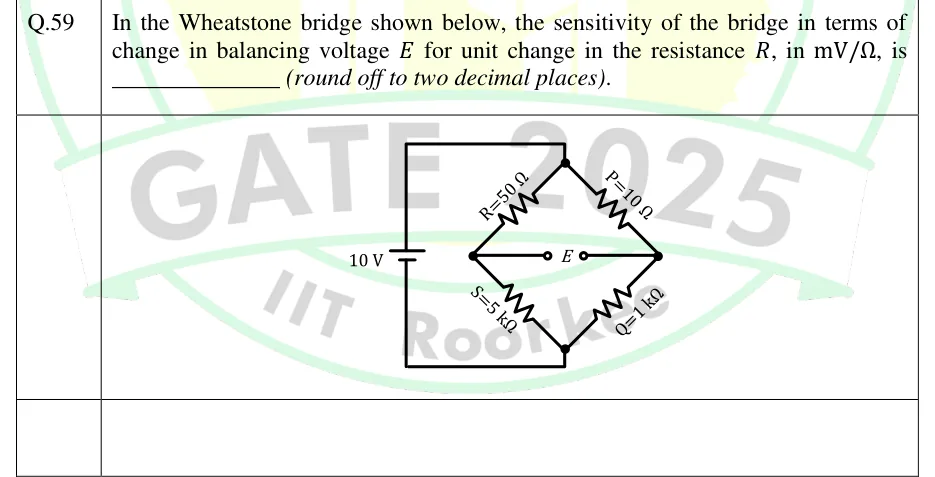
In the Wheatstone bridge shown below, the sensitivity of the bridge in terms of change in balancing voltage for unit change in the resistance , in , is ________ (round off to two decimal places).

GATE 2025 EE question 59: Diamond-shaped Wheatstone bridge with four nodes: top, left, right and bottom.Tap to open full size
Figure from the GATE 2025 EE paper. It is part of the question.
Figure description

Diamond-shaped Wheatstone bridge with four nodes: top, left, right and bottom. Top-left arm (top node to left node): R = 50 Ω. Top-right arm (top node to right node): P = 10 Ω. Bottom-left arm (left node to bottom node): S = 5 kΩ. Bottom-right arm (right node to bottom node): Q = 1 kΩ. A 10 V DC battery sits on a vertical wire at the far left, with its long (positive) plate on top. The top of that wire connects to the top node and the bottom connects to the bottom node, so the top node is at +10 V relative to the bottom node. The detector output E is taken between the left node (R–S junction) and the right node (P–Q junction), drawn as two open terminals marked E.

Answer and solution
GATE 2025 EE Q.59: answer and solution

GATE 2025 IN Q.56

GATE 2025 · INQ.56 · 2 marks · NAT

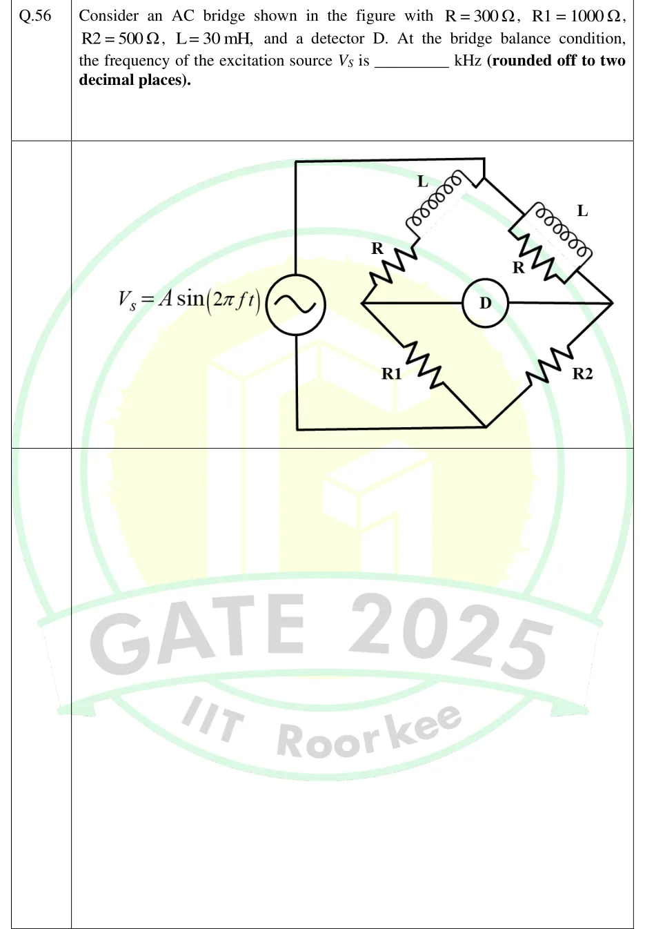
Consider an AC bridge shown in the figure with , , , , and a detector D. At the bridge balance condition, the frequency of the excitation source is ________ kHz (rounded off to two decimal places).

GATE 2025 IN question 56: A four-arm bridge drawn as a diamond with top, left, right and bottom vertices.Tap to open full size
Figure from the GATE 2025 IN paper. It is part of the question.
Figure description

A four-arm bridge drawn as a diamond with top, left, right and bottom vertices. The source V_s = A sin (2 π f t) connects between the top vertex and the bottom vertex. Detector D connects between the left vertex and the right vertex. Top-left arm (left vertex to top vertex): resistor R in series with inductor L. Top-right arm (top vertex to right vertex): resistor R in parallel with inductor L. Bottom-left arm (left vertex to bottom vertex): resistor R1. Bottom-right arm (right vertex to bottom vertex): resistor R2.

Answer and solution
GATE 2025 IN Q.56: answer and solution

GATE 2024 IN Q.39

GATE 2024 · INQ.39 · 2 marks · MCQ

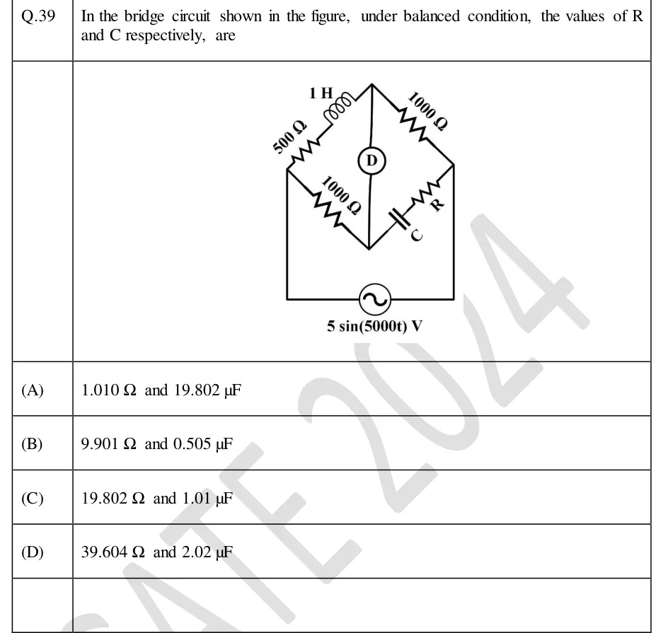
In the bridge circuit shown in the figure, under balanced condition, the values of R and C respectively, are

GATE 2024 IN question 39: A four-arm bridge drawn as a diamond with nodes left, top, right and bottom.Tap to open full size
Figure from the GATE 2024 IN paper. It is part of the question.
Figure description

A four-arm bridge drawn as a diamond with nodes left, top, right and bottom. Arm left-top: a 500 Ω resistor in series with a 1 H inductor. Arm top-right: a 1000 Ω resistor. Arm left-bottom: a 1000 Ω resistor. Arm bottom-right: a capacitor C in series with a resistor R. A detector D is connected between the top and bottom nodes. An AC source 5 sin(5000t) V is connected between the left and right nodes.

  1. (A)

    1.010 Ω and 19.802 μF

  2. (B)

    9.901 Ω and 0.505 μF

  3. (C)

    19.802 Ω and 1.01 μF

  4. (D)

    39.604 Ω and 2.02 μF

Answer and solution
GATE 2024 IN Q.39: answer and solution

GATE 2023 IN Q.30

GATE 2023 · INQ.30 · 1 mark · NAT

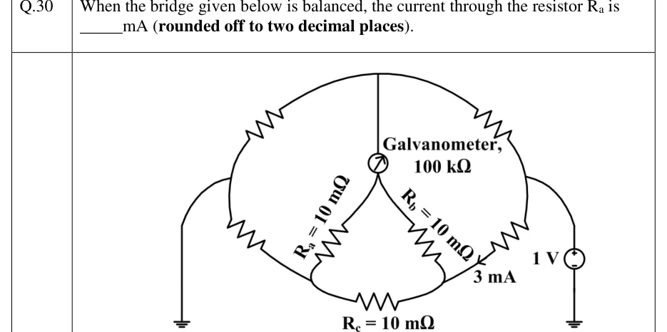
When the bridge given below is balanced, the current through the resistor is ______ mA (rounded off to two decimal places).

GATE 2023 IN question 30: Kelvin-double-bridge-type network drawn as a rounded loop.Tap to open full size
Figure from the GATE 2023 IN paper. It is part of the question.
Figure description

Kelvin-double-bridge-type network drawn as a rounded loop. Nodes: top node T, left node L, right node R, bottom-left node P, bottom-right node Q, and an inner node G. Outer arms (resistors, no values printed): T to L (upper left), L to P (lower left), T to R (upper right), R to Q (lower right). Node L is wired to ground. Node R is wired to the + terminal of a 1 V source whose other terminal is grounded. A galvanometer marked 'Galvanometer, 100 kΩ' connects T (vertical line from the top) to the inner node G. From G, R_a = 10 m Ω goes down-left to P and R_b = 10 m Ω goes down-right to Q. At the bottom, R_c = 10 m Ω connects P and Q. An arrow on the lower-right arm pointing into node Q is labelled 3 mA (the current arriving at Q from the lower-right arm).

Answer and solution
GATE 2023 IN Q.30: answer and solution

GATE 2022 IN Q.63

GATE 2022 · INQ.63 · 2 marks · NAT

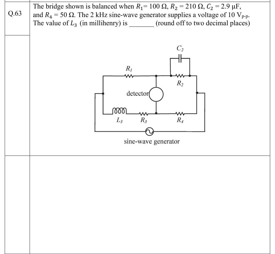
The bridge shown is balanced when , , , and . The 2 kHz sine-wave generator supplies a voltage of . The value of (in millihenry) is ______ (round off to two decimal places)

GATE 2022 IN question 63: Four-arm AC bridge (Maxwell inductance-capacitance bridge).Tap to open full size
Figure from the GATE 2022 IN paper. It is part of the question.
Figure description

Four-arm AC bridge (Maxwell inductance-capacitance bridge). Label the nodes A (left), B (top middle), C (right) and D (bottom middle). Arm A-B (top left): resistor R1. Arm B-C (top right): resistor R2 in parallel with capacitor C2 (C2 drawn above R2). Arm A-D (bottom left): inductor L3 in series with resistor R3. Arm D-C (bottom right): resistor R4. A detector (circle) is connected vertically between B and D. The sine-wave generator is connected between the left node A and the right node C, through wires running below the bridge.

Answer and solution
GATE 2022 IN Q.63: answer and solution

GATE 2022 IN Q.65

GATE 2022 · INQ.65 · 2 marks · NAT

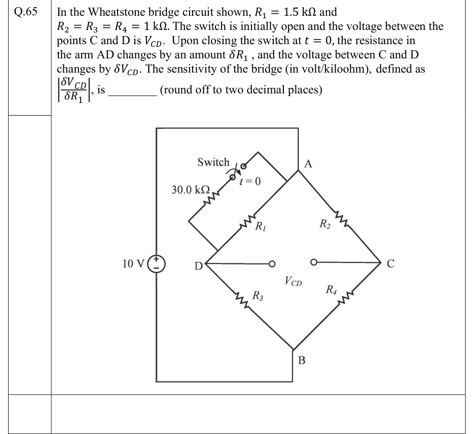
In the Wheatstone bridge circuit shown, and . The switch is initially open and the voltage between the points C and D is . Upon closing the switch at , the resistance in the arm AD changes by an amount , and the voltage between C and D changes by . The sensitivity of the bridge (in volt/kiloohm), defined as , is ________ (round off to two decimal places)

GATE 2022 IN question 65: A diamond-shaped Wheatstone bridge with node A at the top, B at the bottom, D on the left and C on the right.Tap to open full size
Figure from the GATE 2022 IN paper. It is part of the question.
Figure description

A diamond-shaped Wheatstone bridge with node A at the top, B at the bottom, D on the left and C on the right. Arm AD (upper left) is R_1, arm AC (upper right) is R_2, arm DB (lower left) is R_3 and arm CB (lower right) is R_4. A 10 V DC source sits on the left, positive terminal up. Its positive terminal connects by a wire over the top to node A, and its negative terminal connects by a wire along the bottom to node B. The output V_CD is taken between two open terminals joined by wires to D and C. A series branch of a switch (marked 'Switch', closes at t = 0) and a 30.0 kΩ resistor is connected across R_1: one end goes to node A, and the other end goes to arm AD close to node D. Closing the switch therefore puts 30.0 kΩ in parallel with R_1.

Answer and solution
GATE 2022 IN Q.65: answer and solution

GATE 2020 IN Q.54

GATE 2020 · INQ.54 · 2 marks · NAT

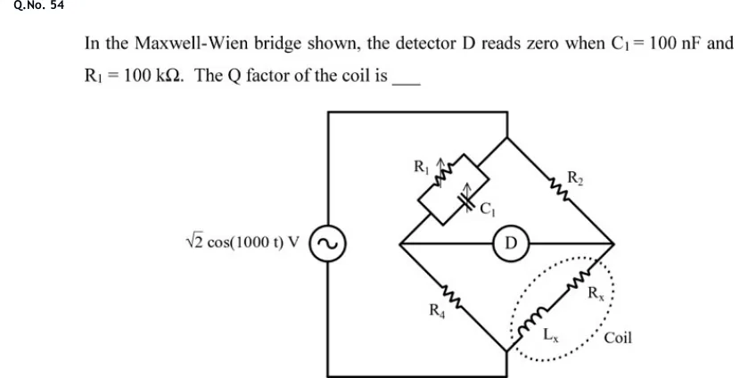
In the Maxwell-Wien bridge shown, the detector D reads zero when and . The Q factor of the coil is ____

GATE 2020 IN question 54: A four-arm bridge drawn as a diamond with a top node, a bottom node, a left node and a right node.Tap to open full size
Figure from the GATE 2020 IN paper. It is part of the question.
Figure description

A four-arm bridge drawn as a diamond with a top node, a bottom node, a left node and a right node. An AC source labelled √ 2 cos (1000 t) V is on the left, connected by wires to the top node and the bottom node. Top-left arm (top node to left node): variable resistor R_1 in parallel with variable capacitor C_1. Top-right arm (top node to right node): resistor R_2. Bottom-left arm (left node to bottom node): resistor R_4. Bottom-right arm (bottom node to right node): the coil, drawn inside a dotted outline labelled 'Coil', made of inductance L_x in series with resistance R_x. Detector D is connected between the left node and the right node. No values are given for R_2, R_4, R_x or L_x.

Answer and solution
GATE 2020 IN Q.54: answer and solution

GATE 2018 IN Q.48

GATE 2018 · INQ.48 · 2 marks · NAT

A high Q coil having distributed (self) capacitance is tested with a Q-meter. First resonance at rad/s is obtained with a capacitance of 990 pF. The second resonance at rad/s is obtained with a 240 pF capacitance. The value of the inductance (in mH) of the coil is (up to one decimal place) ______.

Answer and solution
See the question in the paper
GATE 2018 IN Q.48: answer and solution

GATE 2018 IN Q.49

GATE 2018 · INQ.49 · 2 marks · NAT

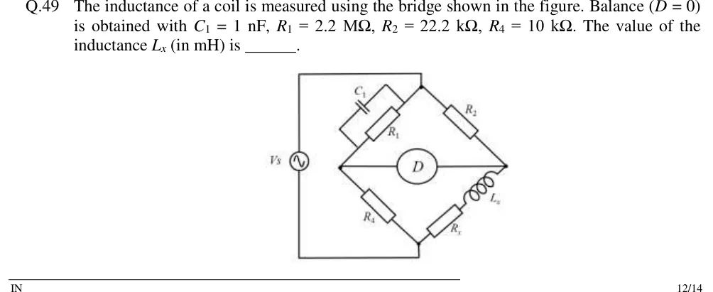
The inductance of a coil is measured using the bridge shown in the figure. Balance () is obtained with , , , . The value of the inductance (in mH) is ______.

GATE 2018 IN question 49: A four-arm bridge drawn as a diamond with top, left, right and bottom nodes.Tap to open full size
Figure from the GATE 2018 IN paper. It is part of the question.
Figure description

A four-arm bridge drawn as a diamond with top, left, right and bottom nodes. Top-left arm (top node to left node): capacitor C1 in parallel with resistor R1. Top-right arm (top node to right node): resistor R2. Bottom-left arm (left node to bottom node): resistor R4. Bottom-right arm (right node to bottom node): the coil under test, inductance Lx in series with its resistance Rx. A detector D is connected across the left and right nodes. An AC source Vs is connected between the top and bottom nodes (drawn to the left of the diamond). This is a Maxwell inductance-capacitance bridge.

Answer and solution
GATE 2018 IN Q.49: answer and solution

PRACTICE

7 questions to test yourself

PRACTICE 11 mark · MCQ

A four-arm AC bridge ABCD has the supply across A and C and the detector across B and D. Arm AB is a coil (resistance and inductance), and arms BC and DA are non-inductive resistors. For the bridge to be balanceable, arm CD must be

  1. (A)

    a non-inductive resistor

  2. (B)

    an inductive impedance whose phase angle equals that of arm AB

  3. (C)

    a capacitive impedance whose phase angle equals that of arm AB in magnitude

  4. (D)

    any impedance, provided its magnitude satisfies

Answer and solution

Answer: (C)

  1. The opposite pairs are AB and CD, and BC and DA, so the phase condition is .

  2. BC and DA are pure resistances, so the right side is zero and .

  3. AB is inductive (), so CD must be capacitive with an angle of the same magnitude, e.g. a capacitor in parallel or in series with a resistor (the Maxwell–Wien and Hay arrangements). The magnitude condition alone (option D) is not enough.

PRACTICE 22 marks · MSQ

A Schering bridge is balanced at 50 Hz. Arm 1 is the capacitor under test, modelled as in series with . Arm 2 is a loss-free standard capacitor pF. Arm 3 (adjacent to arm 1 and opposite arm 2) is a non-inductive resistor . Arm 4 (opposite arm 1) is a non-inductive resistor in parallel with F. Which of the following statements is/are correct?

  1. (A)

    pF

  2. (B)

  3. (C)

    The dissipation factor of the capacitor under test is 0.0628

  4. (D)

    The balance equations for and do not contain the supply frequency

Answer and solution

Answer: (A), (B), (D)

  1. , so and .

  2. pF: A is correct.

  3. : B is correct.

  4. (check: ). C is wrong; 0.0628 would need 100 Hz.

  5. Neither nor contains : D is correct.

PRACTICE 32 marks · NAT

A coil on a Q-meter resonates at 1 MHz with the tuning capacitor set to 460 pF, and at 2 MHz with it set to 100 pF. At 2 MHz the meter indicates Q = 80. Neglecting the shunt resistance and voltmeter loading, and treating the coil's inductance and self-capacitance as constant, the true Q of the coil at 2 MHz is ______.

Answer and solution

Answer: (accepted range )

  1. , so pF.

  2. with pF, the setting at which Q was read: .

  3. Check: H, and MHz.

PRACTICE 41 mark · NAT

The insulation resistance of a cable of capacitance 0.5 μF is measured by the loss-of-charge method. The cable is charged to 500 V and then left to discharge through its own insulation, the voltage being read on an electrostatic voltmeter that draws no current and whose capacitance is negligible. After 60 s the voltage is 250 V. The insulation resistance in MΩ is ______ (rounded off to one decimal place).

Answer and solution

Answer: (accepted range )

  1. .

  2. MΩ.

PRACTICE 51 mark · MCQ

A Wien bridge used to measure frequency has and nF in its series-RC arm, and and nF in its parallel-RC arm. The resistor is opposite the parallel-RC arm and is opposite the series-RC arm. The frequency at which the bridge balances, and the ratio needed for balance, are

  1. (A)

    159 Hz and 2

  2. (B)

    1.59 kHz and 2

  3. (C)

    1.59 kHz and 1

  4. (D)

    10 kHz and 2

Answer and solution

Answer: (B)

  1. Hz kHz.

  2. .

  3. Option D takes rad/s as a frequency in hertz; option C forgets the term.

PRACTICE 61 mark · NAT

A DC slide-wire potentiometer is standardised so that a 1.0186 V standard cell balances at 50.93 cm. With the same working current, a cell balances at 72.40 cm on open circuit and at 65.16 cm when a resistor is connected across its terminals. The internal resistance of the cell in Ω is ______ (rounded off to two decimal places).

Answer and solution

Answer: (accepted range )

  1. Potential gradient V/cm, so the emf is V and the terminal voltage with the resistor connected is V.

  2. Current A, so .

  3. Equivalently, . The standard cell is needed only for the emf, not for .

PRACTICE 72 marks · NAT

A Hay's bridge is balanced at rad/s. Arm 1 is the coil (, ). The arm opposite it is in series with F, and the other two arms are non-inductive resistors and . Using the exact balance equations, the inductance in mH is ______ (rounded off to one decimal place).

Answer and solution

Answer: (accepted range )

  1. , so and .

  2. H mH, which rounds to 495.0 mH.

  3. The high-Q approximation would give 500 mH, 1% high. For completeness, , and .

OFFICIAL GATE 2027 SYLLABUS WORDING

Copied from the GATE 2027 syllabus; see all 2027 syllabi.

GATE EE

Bridges and Potentiometers

GATE IN

bridges: Wheatstone, Kelvin, Maxwell, Anderson, Schering and Wien bridges for measurement of R, L, C and frequency, typical applications of bridges, Q-meter; megohm measurement

Preparing in Kolkata? IAE Academy's course for GATE EE or GATE IN.