
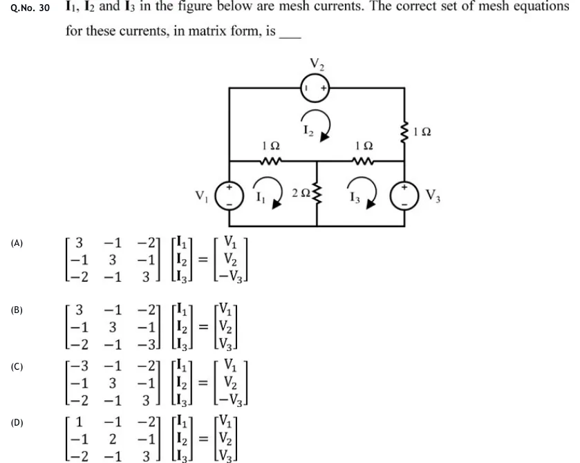
, and in the figure below are mesh currents. The correct set of mesh equations for these currents, in matrix form, is ___
 Tap to open full size
Figure description
A planar circuit with three meshes, all mesh currents drawn clockwise. There are three nodes on a middle horizontal line: left node L, centre node M, right node R. There is a bottom rail and a top rail. Left vertical branch: source V_1 between the bottom rail (−) and node L (+, top). A plain wire runs from node L up to the top-left corner of the top rail. Top rail: source V_2 drawn horizontally, − terminal on the left, + terminal on the right, running from the top-left corner to the top-right corner. Right upper branch: a 1 Ω resistor from the top-right corner down to node R. Middle horizontal: a 1 Ω resistor between L and M, and a 1 Ω resistor between M and R. Centre vertical: a 2 Ω resistor from M down to the bottom rail. Right vertical branch: source V_3 between node R (+, top) and the bottom rail (−). Meshes: I_1 is the lower-left mesh (V_1, L–M 1 Ω, 2 Ω, bottom rail). I_2 is the top mesh (V_2, right 1 Ω, M–R 1 Ω, L–M 1 Ω, left wire). I_3 is the lower-right mesh (M–R 1 Ω, V_3, bottom rail, 2 Ω).
- (A)
- (B)
- (C)
- (D)