
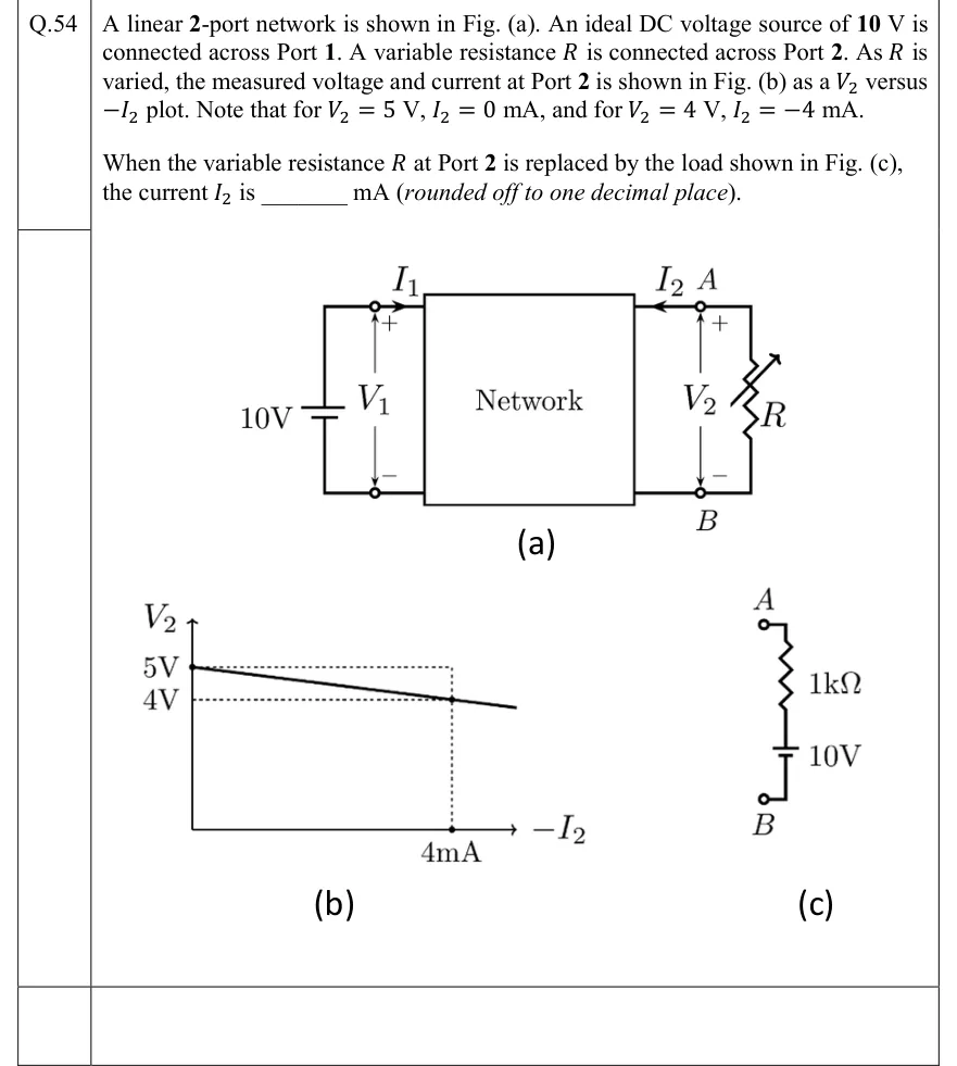
A linear 2-port network is shown in Fig. (a). An ideal DC voltage source of 10 V is connected across Port 1. A variable resistance is connected across Port 2. As is varied, the measured voltage and current at Port 2 is shown in Fig. (b) as a versus plot. Note that for , , and for , .
When the variable resistance at Port 2 is replaced by the load shown in Fig. (c), the current is ________ mA (rounded off to one decimal place).
 Tap to open full size
Figure description
Fig. (a): A box labelled 'Network' with two ports. Port 1 (left): an ideal 10 V battery connected across it, long (positive) plate on top; port voltage V_1 with + at the top terminal and − at the bottom; current I_1 enters the top terminal of port 1 flowing into the network. Port 2 (right): top terminal labelled A, bottom terminal labelled B; port voltage V_2 with + at A and − at B; current I_2 drawn with the arrow pointing from A into the network (i.e. I_2 enters the network at A). A variable resistor R (resistor with a diagonal arrow) is connected between A and B. Fig. (b): Plot of V_2 (vertical axis) versus -I_2 (horizontal axis). A straight line with negative slope starts at V_2 = 5 V on the vertical axis (-I_2 = 0) and passes through V_2 = 4 V at -I_2 = 4 mA (dotted guide lines mark 5 V, 4 V and 4 mA), continuing slightly beyond. Fig. (c): The replacement load between terminals A (top) and B (bottom): from A, a 1 k Ω resistor in series with a 10 V battery down to B; the battery's long (positive) plate faces the resistor/A side and the short (negative) plate faces B (same drawing convention as the port-1 source, whose positive plate is at the V_1 '+' terminal).