
IAE Academy

GATE 2022 IN Q.42: solution and answer

GATE 2022 · INQ.42 · 2 marks · MCQ

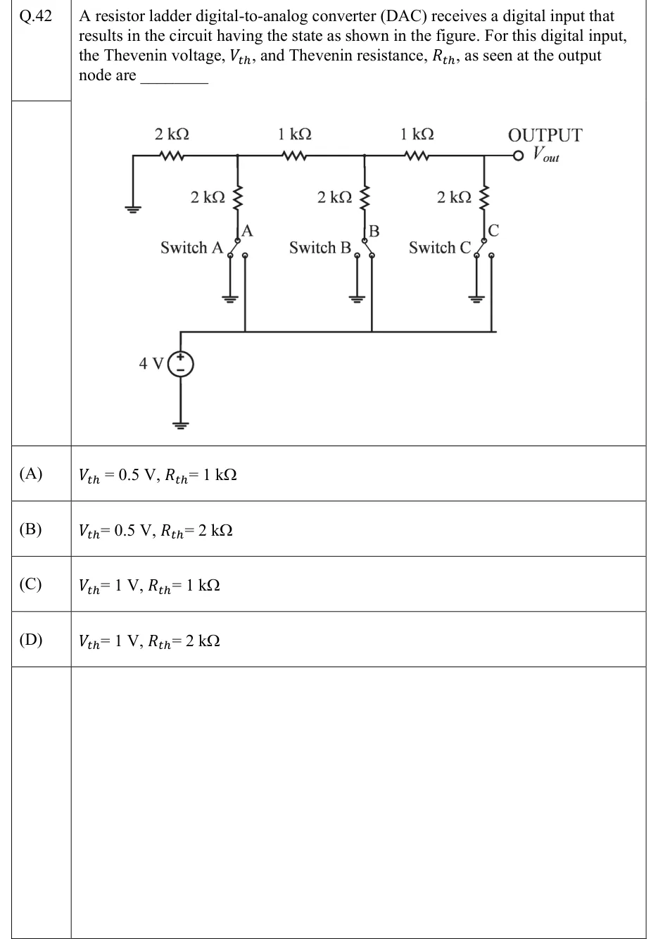
A resistor ladder digital-to-analog converter (DAC) receives a digital input that results in the circuit having the state as shown in the figure. For this digital input, the Thevenin voltage, , and Thevenin resistance, , as seen at the output node are ________
GATE 2022 IN question 42: R-2R ladder.Tap to open full size
Figure from the GATE 2022 IN paper. It is part of the question.
Figure description

R-2R ladder. The top rail runs left to right: its left end goes straight down to ground, then a 2 kΩ series resistor to node A-top, then a 1 kΩ series resistor to node B-top, then a 1 kΩ series resistor to node C-top, which continues to the terminal labelled OUTPUT, V_out. From each of the three rail nodes a 2 kΩ shunt resistor hangs downward to the common pole of a single-pole double-throw switch (labelled A, B, C from left to right, called Switch A, Switch B, Switch C). Each switch has two throws: the left throw goes to ground, the right throw goes to a common horizontal bus that is fed by a 4 V source (positive terminal up to the bus, negative terminal to ground). Switch positions as drawn: Switch A on the left throw (ground), Switch B on the right throw (4 V bus), Switch C on the left throw (ground).

  1. (A)

    ,

  2. (B)

    ,

  3. (C)

    ,

  4. (D)

    ,

Answer and solution

ANSWER

and , which is option (C).

Official answer: CSource: Official answer key, GATE 2022 IN (IIT Kharagpur)

  1. Read the switch states from the figure. Switch A is on ground, Switch B is on the bus and Switch C is on ground. So the three legs end at , and respectively, which is the input code (A, farthest from the output, is the LSB).

  2. Reduce the ladder from the left one node at a time using Thevenin equivalents. At node A the grounded end resistor sits in parallel with leg A, which is also grounded: , .

  3. Add the series resistor to reach node B. The left side becomes behind .

  4. At node B, combine the two sources in parallel using Millman's theorem. One is behind and the other is leg B, behind :

  5. Add the next series resistor to reach node C. The left side is now behind .

  6. At node C, leg C is grounded ( behind ). Millman again:

  7. Node C is the output node, so and .

  8. Check with the R-2R ladder formula with bits. Here and , so . For , killing the source makes every leg end at ground whichever way its switch points, so for every code. This matches option (C).

KEY IDEA

Reduce an R-2R ladder from the far end one node at a time. At every node you get two branches in parallel, so the resistance collapses back to and the Thevenin voltage becomes the average of the two branch voltages (Millman's theorem). Each stage therefore halves whatever came before it, and that gives with for any input code.

WATCH OUT FOR

One common slip is to read the switch blades the wrong way round, or to treat the bit next to the output as the LSB. A 4 V leg at node C would give 2 V, and one at node A would give 0.5 V, which is the trap in options (A) and (B). Another is to take as the leg resistance (options B and D) and forget that the rest of the ladder, which also works out to , sits in parallel with it.

From the GATE 2022 IN paper. Every question of this paper · Download the full paper · All 16 Theorems questions, with notes

More Theorems questions