
IAE Academy

GATE 2020 IN Q.49: solution and answer

GATE 2020 · INQ.49 · 2 marks · NAT

A circuit consisting of capacitors, DC voltage source and an amplifier having a voltage gain G = −5 is shown in the figure. The effective capacitance across the nodes A and B (in µF, rounded off to one decimal place) is ____
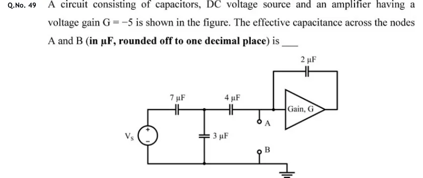
GATE 2020 IN question 49: Ladder circuit with an amplifier.Tap to open full size
Figure from the GATE 2020 IN paper. It is part of the question.
Figure description

Ladder circuit with an amplifier. On the left is a DC voltage source V_s, + terminal at the top and − at the bottom. A top wire runs from V_s(+) through a series 7 µF capacitor to an internal node X. A 3 µF capacitor is connected from node X down to the bottom (common) wire. From node X a series 4 µF capacitor leads to node P. Node P is the input of a triangular amplifier labelled 'Gain, G' that points right. Terminal A is a small open circle hanging just below node P. A 2 µF capacitor is connected between node P (by a wire that rises above the amplifier) and the amplifier output at its right-hand tip, so it is a feedback capacitor from output to input. The bottom wire joins V_s(−), the lower plate of the 3 µF capacitor and terminal B (a small open circle), and ends in a ground symbol at the right. The amplifier output goes nowhere except to the 2 µF capacitor. G = −5.

Answer and solution

ANSWER

The effective capacitance across A and B is .

Official answer: 14.5 to 15.0Source: Official answer key, GATE 2020 IN (IIT Delhi)

  1. Deactivate the source. The capacitance seen between A and B is found with the independent source switched off, so the DC source is replaced by a short circuit. The left end of the 7 µF capacitor is then tied to B (ground). The amplifier is taken as ideal: its input draws no current and its output is a stiff voltage .

  2. Passive branch into A. With the source shorted, the 7 µF and 3 µF capacitors both run from node X to ground, so they are in parallel: . That combination is in series with the 4 µF capacitor:

  3. Miller's theorem for the 2 µF feedback capacitor. The capacitor sits between the amplifier input (A) and its output, where . Its current, flowing out of A, is Seen from A, it therefore behaves as a capacitance to ground of

  4. Combine at node A. Both and run from A to ground (B), so they are in parallel. The ideal amplifier input draws no current, so nothing else loads node A:

  5. Check with a test voltage applied at A. The charge drawn through the 2 µF capacitor is , and through the passive branch it is . So

KEY IDEA

Short the independent DC source, reduce the passive ladder (7 µF parallel with 3 µF, then in series with 4 µF, giving 40/14 µF), and use Miller's theorem on the feedback capacitor: at the input side it looks like to ground, which is 12 µF for G = −5. The two capacitances at A are in parallel.

WATCH OUT FOR

Three slips are common. (1) Getting the Miller sign wrong. Writing with G = −5 gives a negative capacitance, and using the output-side value gives about 5.3 µF. (2) Treating the source as an open circuit, so the 7 µF branch drops out and the passive part becomes , for a total of about 13.7 µF. (3) Putting the 7 µF and 3 µF in series instead of in parallel once the source is shorted.

From the GATE 2020 IN paper. Every question of this paper · Download the full paper · All 16 Theorems questions, with notes

More Theorems questions