
IAE Academy

GATE 2026 EE Q.60: solution and answer

GATE 2026 · EEQ.60 · 2 marks · NAT

Consider the two-port network shown. For maximum power transfer to the resistive load (), the value of should be ________ (Round off to two decimal places)
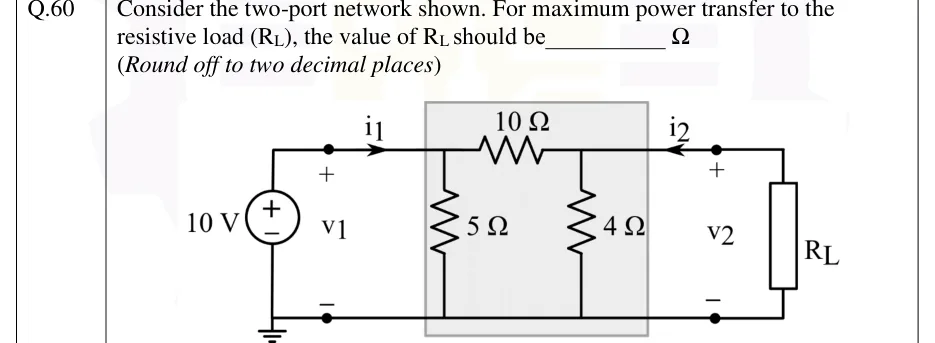
GATE 2026 EE question 60: An ideal 10 V DC voltage source, + terminal on top, drives port 1;Tap to open full size
Figure from the GATE 2026 EE paper. It is part of the question.
Figure description

An ideal 10 V DC voltage source, + terminal on top, drives port 1; its bottom (negative) terminal is on the grounded bottom rail. Port-1 terminals are marked v_1 (+ on top, − at the bottom), and current i_1 flows right into the top terminal of the two-port. The two-port (shaded box) is a pi network: a 5 Ω shunt resistor from the top-left node to the bottom rail, a 10 Ω series resistor along the top from the left top node to the right top node, and a 4 Ω shunt resistor from the top-right node to the bottom rail. Port 2 is on the right: voltage v_2 (+ on top, − at the bottom), with current i_2 flowing left into the top terminal of the two-port. A resistive load R_L is connected across port 2. The bottom rail is common to both ports and grounded at the source side.

Answer and solution

ANSWER

For maximum power transfer, .

Official answer: 2.81 to 2.91Source: Official answer key, GATE 2026 EE (IIT Guwahati)

  1. Maximum power transfer theorem: a resistive load draws maximum power when , the Thevenin resistance seen from port 2 (the terminals of ).

  2. To find , deactivate the independent source: the ideal 10 V source is replaced by a short circuit between the top-left node and the bottom rail.

  3. That short sits directly across the 5 Ω shunt resistor, so the 5 Ω carries no current and drops out. The 10 Ω series resistor, through the short, now connects the port-2 top node to the bottom rail.

  4. Seen from port 2, the 10 Ω path is therefore in parallel with the 4 Ω shunt:

  5. Check (not needed for the answer): with removed, the 5 Ω sits directly across the ideal source and does not affect the rest, so and .

  6. So .

KEY IDEA

Match to the Thevenin resistance at port 2. When the ideal voltage source is replaced by a short, it shorts out the 5 Ω shunt at port 1. That leaves the 10 Ω series arm in parallel with the 4 Ω shunt at port 2.

WATCH OUT FOR

Open-circuiting the voltage source instead of shorting it keeps the 5 Ω in the path and gives , which is wrong. Another mistake is working out two-port parameters (Z or Y) of the pi network alone. That ignores the fact that the ideal source fixes and so shorts port 1 when it is deactivated.

From the GATE 2026 EE paper. Every question of this paper · Download the full paper · All 16 Theorems questions, with notes

More Theorems questions