GATE 2024 IN Q.22
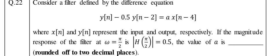
Consider a filter defined by the difference equation
where and represent the input and output, respectively. If the magnitude response of the filter at is , the value of is ________ (rounded off to two decimal places).

IN THE EC AND IN SYLLABUS
FIR and IIR filters are the two families of digital filters. An FIR filter has a finite impulse response, is always stable and can have exactly linear phase. An IIR filter uses feedback and usually meets a magnitude specification with a much lower order, at the cost of stability conditions and nonlinear phase. These notes cover: classifying a linear-phase FIR filter from its symmetry and length; FIR design by windowing and frequency sampling; reading the filter type off a pole-zero plot or difference equation; mapping an analog design to a digital one by impulse invariance or the bilinear transformation (with prewarping); finding a Butterworth or Chebyshev order; and counting the delays and multipliers in a realisation.
2 previous-year questions · 2 solved · 5 practice questions
Conventions used throughout. Digital frequency is in rad/sample and analog frequency is in rad/s. When a digital filter processes samples taken every seconds, an input component at Hz ( rad/s) appears at . (The bilinear transformation in section 4 relates its analog prototype's frequency to differently.) The DTFT is . It is -periodic, so (half the sampling rate) is the highest digital frequency. The z-transform is the bilateral one. Filter coefficients are real. Every filter here is causal, so its ROC is , where is the largest pole radius. A causal filter with a rational is BIBO stable exactly when all its poles, after cancelling common factors, lie inside . An FIR filter has length (order ); in section 5 only, is the order of an analog prototype. The phase is . The group delay is , in samples, taken wherever . Jumps of from wrapping, and jumps of where a real amplitude changes sign, are ignored.
A digital filter is an LTI system described by a constant-coefficient difference equation. If the output depends only on present and past inputs, the impulse response ends after a finite number of samples: a finite impulse response (FIR) filter. If the output also depends on past outputs (feedback), the impulse response in general never ends: an infinite impulse response (IIR) filter.
FIR FILTER OF LENGTH N
Order , taking and . Writing shows that its only poles are poles at . So a causal FIR filter is always BIBO stable.
IIR FILTER AND ITS SIGN CONVENTION
Numerator order , denominator order . The minus sign in the difference equation puts in the denominator. So an equation written as gives , with a pole at . The causal filter is stable if and only if every pole left after cancelling common factors satisfies .
Property | FIR | IIR |
|---|---|---|
Impulse response | finite, samples | infinitely long |
Poles (causal filter) | all at | anywhere; must be inside |
Stability | always BIBO stable | stable only if every pole is inside the unit circle |
Exactly linear phase | possible (symmetric or antisymmetric ) | not possible for a causal, stable filter |
Order for a given magnitude specification | typically much higher | typically much lower |
Usual implementation | non-recursive (no feedback) | recursive (feedback) |
Usual design route | windows, frequency sampling, optimal equiripple | analog prototype mapped by impulse invariance or bilinear transformation |
Finite word-length effects | no limit cycles in non-recursive form; rounding cannot cause instability | limit cycles possible; rounding coefficients can move poles outside the unit circle |
Why a causal, stable IIR filter cannot have exactly linear phase. The usual way to get exact linear phase is symmetry: about some point . Combined with causality ( for ), this forces for , so the response is finite. More generally, exact linear phase makes a real-coefficient rational satisfy . So every non-zero pole comes with a pole at , and a pole inside the unit circle has a partner outside it. A causal filter with a pole outside the unit circle is unstable, so only an FIR filter (all poles at ) escapes. A causal, stable IIR filter can only approximate linear phase. Choose FIR when the waveform shape must be preserved (every frequency delayed by the same number of samples). Choose IIR when a sharp magnitude response is needed with little computation.
EXAM TIP
FIR does not mean non-recursive. The -point moving average can be run recursively as . The pole at is cancelled by a zero of . still has only non-zero samples, so the filter is FIR and stable. The cancellation is exact in exact or integer arithmetic. With rounded arithmetic the pole at accumulates rounding errors, which is why such running sums are normally computed with integers. Decide FIR or IIR from , or from after cancelling common factors, not from the way the equation is written.
An FIR filter has (generalised) linear phase if its coefficients are symmetric or antisymmetric about the midpoint . The symmetry pulls out a pure delay and leaves a real amplitude function . may change sign. Each sign change adds a jump of to the phase but does not change the group delay. Two choices of symmetry times two parities of length give four types.
LINEAR-PHASE CONDITION AND FREQUENCY RESPONSE
is real. Antisymmetry forces the middle sample of an odd-length filter to be zero, since .
GROUP DELAY OF EVERY LINEAR-PHASE FIR FILTER
The same for all four types, at every where . It is an integer for odd (Types I and III) and a half-integer for even (Types II and IV). In seconds it is .
AMPLITUDE FUNCTION OF EACH TYPE
Here ; Types III and IV use . The forced zeros can be read straight off. , so Type II vanishes at . , so Type III vanishes at and . , so Type IV vanishes at .
SYMMETRY IN THE Z-DOMAIN AND THE FORCED ZEROS
Put , where . Symmetric with even: , so . Antisymmetric: , so always. With odd, also , so .
Type | Symmetry | Length | Forced zeros | Cannot be | Suitable for |
|---|---|---|---|---|---|
I | symmetric | odd | none | no restriction | LP, HP, BP, BS |
II | symmetric | even | (so ) | HP, BS | LP, BP |
III | antisymmetric | odd | and | LP, HP, BS | BP, Hilbert transformer |
IV | antisymmetric | even | (so ) | LP, BS | HP, BP, differentiator, Hilbert transformer |
Where the zeros lie. From , if is a zero then so is . Because is real, and are zeros too. So a general complex zero comes in a group of four, . A complex zero on the unit circle comes as a conjugate pair (there ). A real zero other than comes as a pair . Zeros at can occur singly. So a linear-phase FIR filter with a zero strictly inside the unit circle always has its mirror image outside it.
WORKED EXAMPLE
A causal FIR filter has for . Classify it, give its group delay, locate its zeros, and find the kind of filter it is together with the frequency and value of its peak gain.
Compare with : , , . It is antisymmetric with (odd), so it is a Type III filter.
Group delay samples, and .
. Zeros: (simple) and (triple). This matches the forced zeros of Type III, and each zero is its own reciprocal, as the grouping rule requires.
Type III amplitude with : . It is zero at and , so the filter is bandpass.
Peak: (the root is the null at ). So .
. Check with the factored form: .
Answer: Type III linear-phase FIR, group delay 2 samples, zeros at (once) and (three times); a bandpass filter with peak gain at rad/sample.
EXAM TIP
Quick checks on a given . Compare the sequence with its reverse: equal means symmetric, negated means antisymmetric. Judge symmetry between the first and last non-zero samples; extra leading zeros only add samples to the group delay. An antisymmetric odd-length sequence must have a zero centre sample. The coefficient sum is and the alternating sum is . If the alternating sum is zero, the filter cannot be highpass.
The ideal lowpass response (gain 1 for , 0 for ) has an infinitely long, non-causal impulse response. The window method delays it by so that it is centred on the window. It then multiplies it by a length- window that is zero outside . The result is causal, finite and linear phase (Type I or II), because both the delayed ideal response and the window are symmetric about .
DELAYED IDEAL LOWPASS IMPULSE RESPONSE
is in rad/sample. It is written with explicitly, so no sinc convention is needed. The centre value is the limit as . For even , is a half-integer and no sample falls at .
OTHER IDEAL RESPONSES BUILT FROM THE LOWPASS
The term needs an integer , i.e. odd . So a windowed highpass or bandstop design is Type I, consistent with the forced zero at that rules out Type II.
WINDOWING IN TIME IS CONVOLUTION IN FREQUENCY
The main lobe of smears each ideal band edge into a transition band. Its side lobes create ripple in the passband and the stopband.
COMMON WINDOWS (0 TO N-1, ZERO ELSEWHERE)
For . This is one common form; some texts use in place of so that the end samples of the Hann window are not zero. All four are symmetric about , so linear phase is kept. The Hamming window's end samples are , not zero.
Window | Main-lobe width, null to null (approx.) | Peak side lobe of (approx.) | Minimum stopband attenuation of the filter (approx.) |
|---|---|---|---|
Rectangular | dB | dB | |
Hann | dB | dB | |
Hamming | dB | dB | |
Blackman | dB | dB |
Reading the table (all values approximate, for large ). Going down the table, the side lobes fall, giving better stopband attenuation. But the main lobe widens, giving a wider transition band for the same . The transition width is roughly proportional to , so increasing sharpens the edge. The attenuation, however, is fixed by the shape of the window and does not improve with . So choose the window from the required stopband attenuation, then choose from the required transition width.
For instance, take , () and a rectangular window: , , , and . The DC gain is , not 1: the samples of that the window discards sum to .
FREQUENCY-SAMPLING DESIGN
This is the -point inverse DFT, with so that . The designed response passes exactly through the specified samples and is interpolated between them. For a real, linear-phase Type I result ( odd), take with .
Between the samples the response can ripple strongly next to an abrupt jump from 1 to 0. Placing one or two intermediate-valued transition samples in the transition band trades a slightly wider transition for much lower stopband ripple. Frequency sampling is convenient when the desired response is specified at the DFT frequencies .
EXAM TIP
Gibbs phenomenon. With the rectangular window, the ripple next to the cut-off does not shrink as grows. The overshoot stays at roughly 9% of the jump (about 21 dB stopband attenuation) and only moves closer to the edge. A statement such as "doubling halves the ripple of a rectangular-window design" is false; doubling roughly halves the transition width. To get lower ripple, change the window.
IIR filters are usually designed by taking an analog prototype (Butterworth, Chebyshev, elliptic) and mapping the -plane to the -plane. A good mapping sends the axis onto the unit circle, so the frequency response carries over. It also sends the left half-plane inside the unit circle, so stability carries over.
IMPULSE INVARIANCE
Needs a strictly proper with simple poles (do the partial fractions first). The sample at uses . Each analog pole becomes the digital pole ; zeros do not map by this rule. With the factor , for when aliasing is small. Some texts use without it, which scales by , so check which one a question uses.
FREQUENCY RESPONSE UNDER IMPULSE INVARIANCE
With . This is exact when is continuous at , i.e. when the denominator degree of exceeds the numerator degree by at least 2. If jumps at , the sum equals . The frequency axis maps linearly (, no warping), but shifted copies overlap: this is aliasing. It is small only if for .
A stable analog pole () gives , so impulse invariance preserves stability. But the map is many-to-one: every horizontal strip of height in the -plane lands on the whole -plane except the origin. Highpass and bandstop prototypes do not fall to zero at high frequency, so their shifted copies overlap badly. Impulse invariance is therefore unsuitable for highpass and bandstop filters. It is used for band-limited lowpass and bandpass designs, or when the sampled shape of the impulse response itself must be kept.
BILINEAR TRANSFORMATION
Substitute into to get an of the same order. The whole left half -plane maps inside , so stability is preserved. The entire axis maps once onto the unit circle: goes to and goes to . There is no aliasing.
FREQUENCY WARPING OF THE BILINEAR TRANSFORMATION
in rad/s (analog), in rad/sample (digital). The relation is nearly linear, , only for small . The whole infinite analog axis is squeezed into .
Bilinear design with prewarping, in order:
Write the digital band edges , in rad/sample, using if they are given in hertz.
Prewarp each critical edge: . If the specification is purely digital, any works; gives the tidy and . If it is given in hertz with a sampling rate and you need the analog edges in rad/s, use .
Design the analog prototype to meet the specification at the prewarped edges: first the order, then the poles.
Substitute with the same . cancels, so the final does not depend on it.
Check , the gain at , and that every pole is inside the unit circle. An analog zero at becomes a digital zero at .
Property | Impulse invariance | Bilinear transformation |
|---|---|---|
Mapping | , applied to the poles | , applied to the whole |
Frequency axis | linear, | warped, |
Aliasing | yes | none |
Stability preserved | yes | yes |
Filter types | band-limited LP and BP; not HP or BS | LP, HP, BP, BS |
What is kept | the sampled impulse response | the piecewise-constant magnitude shape; not the phase or the impulse response |
Prewarping needed | no | yes, at the critical band edges |
EXAM TIP
Forgetting to prewarp. Without prewarping, a bilinear design puts its cut-off at , which is always below . For example, rad gives rad/sample instead of 1.5. The warping matters most for edges close to .
EXAM TIP
Backward-difference mapping. Replacing by a backward difference gives , i.e. . It also maps the left half -plane to a stable region. But it sends the axis onto the circle , not onto the unit circle, so the frequency response carries over only for . This is why the bilinear transformation is preferred.
BUTTERWORTH MAGNITUDE RESPONSE
Order (in this section is the prototype's order, not an FIR length), cut-off in rad/s. and , i.e. dB at the cut-off for every . The response is monotonic in both bands. It is maximally flat: the first derivatives of are zero at . The asymptotic roll-off is dB/decade.
BUTTERWORTH ORDER
is the maximum attenuation (dB) allowed over the passband . Because the response is monotonic, the attenuation there is largest at . is the minimum stopband attenuation (dB) at . Round up to the next integer. If the passband edge is the 3-dB cut-off ( dB, ), then .
CUT-OFF FOR THE CHOSEN ORDER
Or to meet the stopband exactly. Once has been rounded up, any between these two values meets both specifications.
BUTTERWORTH POLES
The poles are equally spaced by on a circle of radius , all in the left half-plane and symmetric about the real axis. There is a real pole at only when is odd.
NORMALISED BUTTERWORTH DENOMINATORS (UNIT CUT-OFF)
For a cut-off , replace by . Each quadratic factor is for , with a factor added when is odd. For the factor has damping ratio .
CHEBYSHEV TYPE I (IN BRIEF)
Equiripple in the passband, monotonic in the stopband. Passband ripple dB. At DC, for odd and for even . obeys with , .
CHEBYSHEV TYPE I ORDER
Same and as for Butterworth, with the edge of the ripple band and equal to the passband ripple, so . Round up.
ANALOG FREQUENCY TRANSFORMATIONS (FROM A LOWPASS PROTOTYPE WITH CUT-OFF 1 RAD/S)
Here and . The prototype's edge at rad/s lands on , or on and . The bandpass and bandstop substitutions double the order. In a bilinear design, prewarp every digital edge first, then apply the substitution to the prototype.
Comparing prototypes for the same specification. Of these, Butterworth needs the highest order. Chebyshev Type I (ripple in the passband) and Type II (monotonic passband, ripple in the stopband) need a lower order, the same for both. Elliptic (ripple in both bands) needs the lowest. Butterworth has the gentlest phase variation near the band edge; Chebyshev and elliptic buy sharpness with ripple and more phase nonlinearity. Both mapping methods keep the order: an th-order prototype gives an th-order digital filter.
WORKED EXAMPLE
Using the bilinear transformation, design a digital Butterworth lowpass filter with its 3-dB cut-off at rad/sample and an attenuation of at least 15 dB for . Find the minimum order and .
Take (it cancels), so and .
Prewarp: rad/s and rad/s.
Order, with the passband edge at the 3-dB point: , so .
Prototype with : .
Substitute and multiply through by . The denominator becomes ; the terms cancel.
So , using and .
Checks: . At (), : , i.e. dB. Poles at , inside the unit circle. The double zero at is the image of the prototype's zeros at .
Stopband: at the attenuation is dB, which meets the 15 dB requirement.
Answer: and .
EXAM TIP
Specification given as a gain. Convert first: a gain of is an attenuation of dB. A passband gain of at least 0.9 means dB; a stopband gain of at most 0.1 means dB. Equivalently, can be put straight into the order formula.
On the unit circle , the factor is the distance from the point at angle to a zero, and the distance to a pole. The gain at is the product of the zero distances divided by the product of the pole distances, times the constant gain. So a zero on the unit circle at angle gives a null at , and a pole close to the unit circle at angle gives a peak there. The point is (DC) and is .
GAIN FROM THE POLE-ZERO PLOT
This uses . Poles or zeros at the origin are at distance 1 from every point on the circle, so they change only the phase.
Filter | Typical pole-zero pattern | Simple example |
|---|---|---|
Lowpass | zeros at or near ; poles, if any, near | ; or with (unit DC gain) |
Highpass | zeros at or near ; poles, if any, near | ; or with (unit gain at ) |
Bandpass | zeros at ; complex poles near | , peak at |
Bandstop or notch | zeros on the unit circle at ; poles just inside at the same angles | , null at |
All-pass | each pole paired with a zero at , its mirror image in the unit circle | , real , |
Comb | zeros equally spaced on the unit circle |
SECOND-ORDER NOTCH FILTER
Zeros at give an exact null at ; poles at . The closer is to 1, the narrower the notch. With close to 1, the gain away from is close to 1. Without the poles, is an FIR notch with a much wider dip.
ALL-PASS FILTER
Pole at , zero at . Higher orders are products of such sections. With a real denominator of order , , i.e. the numerator coefficients are the denominator coefficients in reverse order. Used to correct phase (delay) without changing the magnitude.
L-POINT MOVING AVERAGE
A lowpass, symmetric (Type I or II) FIR filter with DC gain 1 and group delay . Its zeros are at , (the zero cancels the pole at ), so it has nulls at .
COMB FILTERS
is an integer. removes DC and every multiple of , for example a mains frequency and its harmonics when equals the mains frequency. Both are linear-phase FIR filters (antisymmetric and symmetric respectively) with group delay .
EXAM TIP
Four short filters to recognise on sight. (zero at ) is lowpass, . (zero at ) is highpass, . (zeros at ) is bandpass, , peak at . (zeros at ) is bandstop, , null at . For any filter, and settle lowpass versus highpass in seconds.
EXAM TIP
Lowpass to highpass in one step. Replacing by in (i.e. ) turns into and into . The response shifts by , so a lowpass with cut-off becomes a highpass with passband . Every pole and zero moves to its negative. For example, becomes .
EXAM TIP
A causal filter with any pole outside the unit circle is unstable, whatever its zeros do. An uncancelled pole exactly on the circle makes it marginally stable at best, which is not BIBO stable. That is why a notch filter or resonator puts its poles at a radius .
A realisation is a block diagram built from adders, multipliers and unit delays (). Different structures realise the same but differ in memory (delays), arithmetic (multipliers) and sensitivity to coefficient rounding. Below, an IIR filter is with numerator order and denominator order (as in section 1), and an FIR filter has length .
DIRECT FORM II (CANONIC) EQUATIONS
The all-pole part comes first and the all-zero part second, so both share one delay line holding . Direct form I uses the opposite order ( first, then ) and needs separate delay lines for and .
Structure | Delays | Multipliers (general coefficients) | Remarks |
|---|---|---|---|
Direct form I | separate input and output delay lines; not canonic | ||
Direct form II | canonic: minimum number of delays | ||
Transposed direct form II | reverse every branch and swap input and output; same by the transposition theorem | ||
Cascade | (for ) | up to 5 per second-order section () | with first- and second-order sections; low coefficient sensitivity |
Parallel | (for ) | 4 per second-order section (), plus a constant if | partial fractions of in ; low coefficient sensitivity |
FIR direct form (tapped delay line) | also called the transversal structure | ||
Linear-phase FIR | add the two samples that share a coefficient before multiplying; Type III needs one fewer, since its centre coefficient is zero |
Counting multipliers. The counts above treat every and as a general number. A coefficient equal to needs no branch, and one equal to needs no multiplier (only an adder or subtractor). So for a specific , count only the coefficients that are not or . The number of delays in a canonic structure equals the order of , which is after common factors have been cancelled.
EXAM TIP
Cancel before counting. realised as written in direct form II uses 2 delays. But it equals , which needs only 1. When a question asks for the minimum number of delays, simplify first.
EXAM TIP
High-order IIR filters are rarely built in direct form. Rounding the coefficients of a high-degree polynomial can move its roots a long way and push poles outside the unit circle. Cascade or parallel second-order sections let each pole pair depend on only its own two coefficients. An FIR direct form has no feedback, so coefficient rounding changes the response slightly but can never make it unstable. Linear phase survives rounding because symmetric coefficients stay symmetric.
PREVIOUS-YEAR QUESTIONS
Try each question first, then open the answer. We placed each question under a topic ourselves; the exam paper does not label topics.
See these papers in full: GATE IN 2024 · GATE IN 2022
Consider a filter defined by the difference equation
where and represent the input and output, respectively. If the magnitude response of the filter at is , the value of is ________ (rounded off to two decimal places).
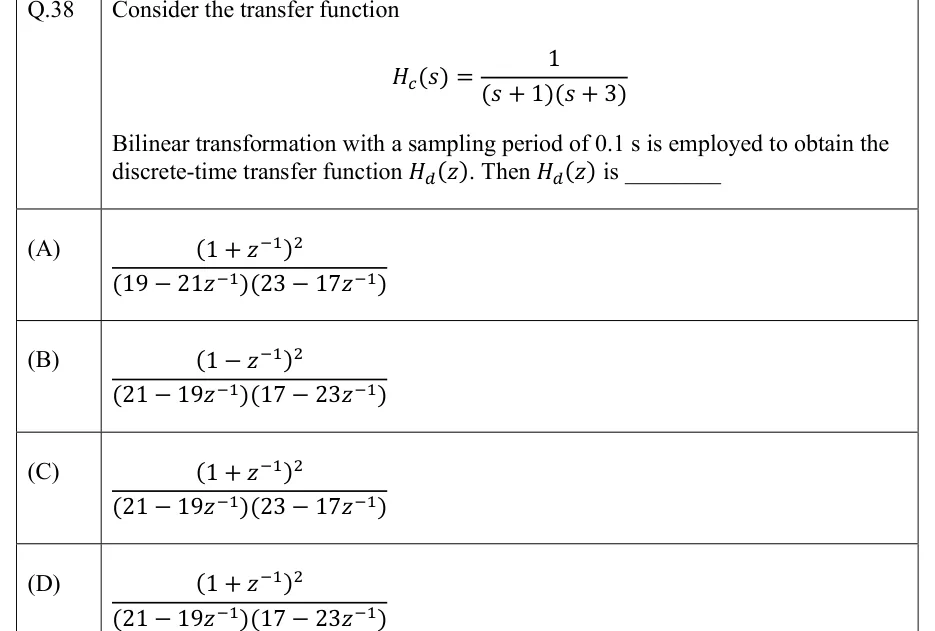
Consider the transfer function
Bilinear transformation with a sampling period of 0.1 s is employed to obtain the discrete-time transfer function . Then is ________
PRACTICE
A causal FIR filter has an impulse response of length 8 that satisfies for . Which one of the following filters cannot be designed with such an impulse response?
Lowpass
Bandpass
Highpass
A lowpass filter with a group delay of 3.5 samples
Answer: (C)
Symmetric with (even): a Type II linear-phase FIR filter.
Symmetry gives . At : , so , i.e. for every such filter.
A highpass filter needs non-zero gain at , so it is impossible. Lowpass and bandpass are possible, and every Type II filter has group delay samples, so (D) is possible too.
A digital Butterworth lowpass filter is to be obtained by the bilinear transformation with prewarping. Specification: attenuation at most 1 dB for and at least 20 dB for , with in rad/sample. The minimum order of the filter is ______.
Answer:
Prewarp with (any gives the same ratio): and .
, and .
, so .
Check: with and the passband met exactly, the attenuation at is dB, below 20 dB; with it is dB.
The analog filter is converted to a digital filter by impulse invariance, using with s. With coefficients rounded to four decimal places, the digital transfer function is
Answer: (A)
Partial fractions: , with poles at and .
Each term becomes : , with and .
Combine over the common denominator: numerator ; denominator .
(B) omits the factor ; (C) has the wrong sign on the term, which would put the poles at and ; (D) loses the delay, although here.
A digital lowpass IIR filter is designed by the bilinear transformation with and sampling frequency kHz. The digital filter's cut-off must be at 2 kHz. The prewarped cut-off frequency of the analog prototype, in rad/s, is ______.
Answer: (accepted range )
Digital cut-off: rad/sample.
Prewarp: rad/s.
Using the unwarped value rad/s instead would put the digital cut-off at rad/sample, about 1.70 kHz, not 2 kHz.
A causal system with zero initial conditions is implemented as . Which of the following statements is/are TRUE?
Its impulse response is non-zero for exactly 8 values of .
It is not BIBO stable, because the factor in the denominator of gives a pole at .
at rad/sample.
Its group delay is 4 samples.
Answer: (A), (C)
, the 8-point moving average: for and 0 otherwise. (A) is true.
The zero of at cancels that pole, and , so the system is BIBO stable. (B) is false.
The zeros are at , ; gives a null at . Equivalently at . (C) is true.
is symmetric with length 8, so the group delay is samples. (D) is false.
OFFICIAL GATE 2027 SYLLABUS WORDING
Copied from the GATE 2027 syllabus; see all 2027 syllabi.
GATE EC
FIR and IIR filter design
GATE IN
basics of IIR and FIR filters
Preparing in Kolkata? IAE Academy's course for GATE ECE or GATE IN.