
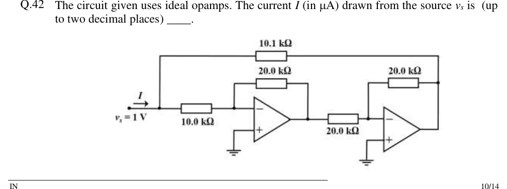
The circuit given uses ideal opamps. The current (in A) drawn from the source is (up to two decimal places) ____.
 Tap to open full size
Figure description
A source v_s = 1 V drives a node; the current I flows from the source into that node (arrow pointing right). From this node, a 10.0 k Ω resistor goes to the inverting (−) input of op-amp 1, and a 10.1 k Ω resistor runs along the top of the drawing to the output of op-amp 2. Op-amp 1: non-inverting (+) input grounded, 20.0 k Ω feedback resistor from its output to its inverting input. The output of op-amp 1 feeds a 20.0 k Ω resistor into the inverting (−) input of op-amp 2. Op-amp 2: non-inverting (+) input grounded, 20.0 k Ω feedback resistor from its output to its inverting input. The output of op-amp 2 is also the right-hand end of the 10.1 k Ω resistor that goes back to the source node.