
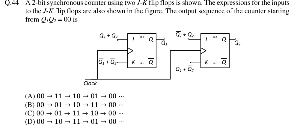
A 2-bit synchronous counter using two - flip flops is shown. The expressions for the inputs to the - flip flops are also shown in the figure. The output sequence of the counter starting from is
 Tap to open full size
Figure description
Two J-K flip-flops (each box labelled J, K, Q, Q-bar, SET, CLR) share one Clock line, so the counter is synchronous. The clock-input triangle carries no bubble (positive-edge triggered as drawn). Left flip-flop: output Q is labelled Q_1; its J input is labelled Q_1 + Q_2 and its K input is labelled Q_1 + Q_2. Right flip-flop: output Q is labelled Q_2; its J input is labelled Q_1 + Q_2 and its K input is labelled Q_1 + Q_2. SET and CLR are left unconnected. (Overbar = complement.)
- (A)
- (B)
- (C)
- (D)