
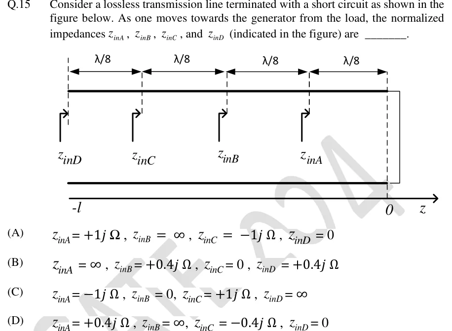
Consider a lossless transmission line terminated with a short circuit as shown in the figure below. As one moves towards the generator from the load, the normalized impedances , , , and (indicated in the figure) are ________.
 Tap to open full size
Figure description
A two-wire lossless transmission line drawn horizontally (two thick parallel lines). At the right end (z = 0) the two conductors are joined by a vertical wire, i.e. a short-circuit load. A z-axis runs left to right beneath the line, with the right end marked 0 and the left end marked -l. Vertical dashed lines divide the line into four equal segments, each labelled λ/8 with double-headed arrows along the top. Moving from the load (z = 0) towards the generator (left): the first dashed line (distance λ/8 from the load) is labelled z_inA, the second (distance λ/4) is labelled z_inB, the third (distance 3λ/8) is labelled z_inC, and the fourth, at the left end z = -l (distance λ/2), is labelled z_inD. Each label has a right-pointing bent arrow indicating the impedance looking towards the load.
- (A)
, , ,
- (B)
, , ,
- (C)
, , ,
- (D)
, , ,