
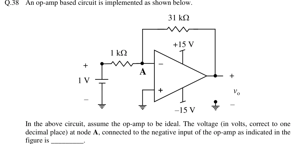
Q.38 An op-amp based circuit is implemented as shown below.
[Figure]
In the above circuit, assume the op-amp to be ideal. The voltage (in volts, correct to one decimal place) at node A, connected to the negative input of the op-amp as indicated in the figure is ________.
 Tap to open full size
Figure description
An inverting amplifier. A 1 V DC source (battery, + terminal on top, − terminal to ground) connects through a 1 kΩ resistor to node A. Node A is the op-amp's inverting (−) input. A 31 kΩ feedback resistor connects node A to the op-amp output. The non-inverting (+) input is grounded. The op-amp is powered from +15 V (top rail) and −15 V (bottom rail). The output node is labelled v_o (+ at the output, − at ground).