
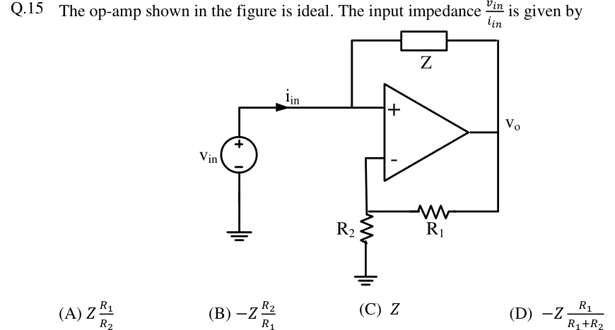
The op-amp shown in the figure is ideal. The input impedance is given by
 Tap to open full size
Figure description
An ideal op-amp with its non-inverting (+) input at the top and its inverting (-) input at the bottom; output node labelled V_o on the right. A voltage source v_in (+ terminal up, - terminal to ground) drives a current i_in (arrow pointing right, toward the op-amp) into the node at the non-inverting (+) input. An impedance Z connects this non-inverting input node to the output V_o (drawn above the op-amp). The inverting (-) input goes to a node that is grounded through resistor R_2 and connected to the output V_o through resistor R_1 (drawn below the op-amp). So R_1 and R_2 form a divider from V_o to ground, with the tap at the inverting input.
- (A)
- (B)
- (C)
- (D)